Important changes to forums and questions
All forums and questions are now archived. To start a new conversation or read the latest updates go to forums.mbed.com.
9 years, 10 months ago.
ADC OUTPUT FLUCTUATIONS CHALLENGE?????
#include "mbed.h"
Serial pc(USBTX,USBRX);
DigitalOut myled(LED2);
int i=0;
int deep[100];
void initadc()
{
  pc.printf("in adc\n");
  LPC_SC->PCONP|=(1<<1);////power up timr
  LPC_SC->PCONP|=(1<<15);/// SELECT PCONP GPIO 15th pin
  LPC_SC->PCONP|=(1<<12);/// SELECT PCONP PCADC 12TH pin
  LPC_SC->PCLKSEL0 &= ~(1<<24);
  LPC_SC->PCLKSEL0 &= ~(1<<25);//SETTING UP OF CCLK for 25Mhz;
  int CCLK = LPC_ADC->ADCR|=(1<<8); ///SET PRESCALAR VALUE /1 so that it works at 13mhz;ie works at 12.5 Mhz
  pc.printf("cclkvalue is %d\n",CCLK);
  LPC_PINCON->PINSEL1|=(1<<14);/// select pin (p0.23 ad0.0)
  LPC_PINCON->PINMODE1|=(2<<15);///
  LPC_ADC->ADCR |=(1<<21); //ADC on
  LPC_ADC->ADINTEN |=(1<<0); /// interrupt enable on dis pin
}
void initchan(int ch)
{
 LPC_ADC->ADCR|=(1<<ch);//SELECT CHANNEL(SEL BITS)
 pc.printf("in channel");
}
void initpcon()
{
   pc.printf("in pconp\n");
   LPC_SC->PCONP|=(1<<1);////power up timr
   LPC_SC->PCLKSEL0 &=~(1<<2)|~(1<<3); ////////cclk/4=25mhz;
}
void inittimer()
{
     pc.printf("intimer\n");
     LPC_TIM0->CTCR&=~(1<<0);////init timer
     LPC_TIM0->TCR=(1<<1);////RESET TIMER
     LPC_TIM0->PR=0x00;
     LPC_TIM0->MR0= 2500;
     LPC_TIM0->MCR =(3<<0);///ENABLE TIMER0 INTERRUPT
 }

 void deepu()
 {

      while((LPC_TIM0->IR&0x01)!=0x01);///wait till it matches the TC value of MRO
      LPC_ADC->ADCR |= (1<<24); // START = start conversion now
      while ((LPC_ADC->ADGDR & (0x80000000))==0); //wait till done bit in adcr is set/* Wait for Conversion end */
      deep[i] = (LPC_ADC->ADDR0 >> 4) & 0xFFF;
      LPC_ADC->ADCR &= ~(1<<24);///stop adc conversion
      LPC_TIM0->IR|=(1<<0); ///AND disable
      LPC_TIM0->MCR&=~(1<<0);
      pc.printf("%f\n",(float)(deep[i]*((float)3.3/4096)));
      myled=!myled;
       }
void lool()
{
     LPC_TIM0->MCR =(3<<0);/// ENABLE INTERRUPT TIMER AND RESET
     NVIC_EnableIRQ(TIMER0_IRQn);
     LPC_TIM0->TCR=(1<<0);
}
 int main()
 {
     //int i;
     initadc();
     initchan(0);
     initpcon();
     inittimer();
     NVIC_SetVector(TIMER0_IRQn,(uint32_t)&deepu);

    /// inittimer();

while(1)
{
        lool();
 }
  }


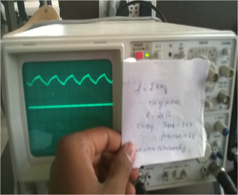
hi i am trying to plot the values of adc which i get it on tera term on spread sheet, each time i get a fluctation lik dis can any one suggest me the problem what is wrong . i have attached my code also wid dis.the signal input is 1khz the mro value given is 2500(i,e 10khz) i need to plot a pure wave as in that of cro with very less fluctuation can anyone suggest me a good solution to my code ,
2 Answers
9 years, 10 months ago.
In general just first try to do it using the mbed libs, so in this case AnalogIn. See what kind of results you will get, then when that works you can look at making your own ADC code if you want to do that.
In general, although the disturbances shown are quite large: make sure you got a normal, stable power supply without something like a motor on the same supply. Connect both ground and signal of your signal source to your mbed, preferably keeping the two wires together for as long as possible. The output impedance of the source may not be larger than 7.5kOhm according to datasheet, and also no large capacitances are allowed there. So if you are making the signal with an RC filter and measuring directly on there, that might be an issue. Finally what is good practise, although it won't give errors as large as shown here: Set the neighbouring pins to DigitalOut, that decreases errors.
hi i tried those codes(ANALOG IN ,READ) could not find suitable results, i thought of sampling
my aim of this program is
the input frequency given is 1 khz
the MRO=2500;so that pclk(1/25mhz=40ns) and considered sampling is (1/10khz) =0.0001sec so (0.0001/40 ns)=2500
so that it calls the interrupt for 0.0001 sec and reads the value
Is my approach correct or should i use any other logic
I NEED TO GET A EXACT WAVE SIMILAR THAT WHICH I HAVE POSTED
I AM LEFT WITH 1 MORE DAY OR ELSE MY SENIOR STARTS GRUMBLING
CAN ANYBODY PLS LET ME KNOW THE SOLUTION......
posted by 03 Jun 20149 years, 10 months ago.
Hi
I can only point to an old thread i started on this subject. It contains one line that influences the number of spikes very much.
https://mbed.org/forum/mbed/topic/2919/?page=1#comment-14949
I never got to the real cause (although setting up the neighboring adc pins and tying them to ground seemed to improve even more)
I ended up by adding a simple filter comparing 3 points and set the middle point to the average of the other two if it differed to much (ie was a spike).
Another observation was that DMA driven conversion starts emitting wrong channel numbers (kind of slipping it seems) at certain higher timing rates.
For this i ended up with overclocking the cpu clock to be dividable by 65 and do DMA driven conversion every msec in my case. Lowed rates i archive by skipping converted points (you could also average them).
regards