Important changes to forums and questions
All forums and questions are now archived. To start a new conversation or read the latest updates go to forums.mbed.com.
11 years, 8 months ago.
PWM range reduced after optocoupler
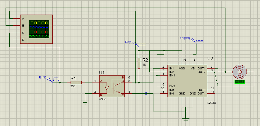
I am using STM32F4 to generate a PWM signal to control a DC motor. I have attached an optoisolator/optocoupler to isolate my MCU and the driving circuit. the optocoupler (4N35) is attached to H bridge (L293D) to drive the DC motor.
My simulated design on proteus works fine (I have just provided a pulse input to the optocoupler...no controller used in simulation) as I can observe motor speed decreasing as modulation is decreased. However, my practical implementation has me baffled. Somehow my PWM range has been reduced, varying the modulation in the region of 3% to 6% the DC motor speed varies from 0 to full.
However, if i directly connect my microcontroller to the H bridge, the modulation is as expected.
Is there a flaw in my design? (I do not know why simulation is working). Also, my PWM signal is of 20kHz...is that causing the optoisolator to behave funny?.

1 Answer
11 years, 8 months ago.
you might have a SLOW opto-optocoupler,
Assuming you have fitted these values, it should be OK,
you could try putting the opto on the Hi-Side (in place of R2)
dont forget you have basically INVERTED the signal from micro ..
led = on, -> Transistor = on, pulling Collector LOW
Hope this helps
Ceri
It helped! My range of pulse modulation has increased but there is still a little problem...at low modulation like 12.5% or so the DC motor stops and starts generating a high pitched noise.
posted by 09 Apr 2014