Important changes to forums and questions
All forums and questions are now archived. To start a new conversation or read the latest updates go to forums.mbed.com.
10 years, 2 months ago.
CAN Communication
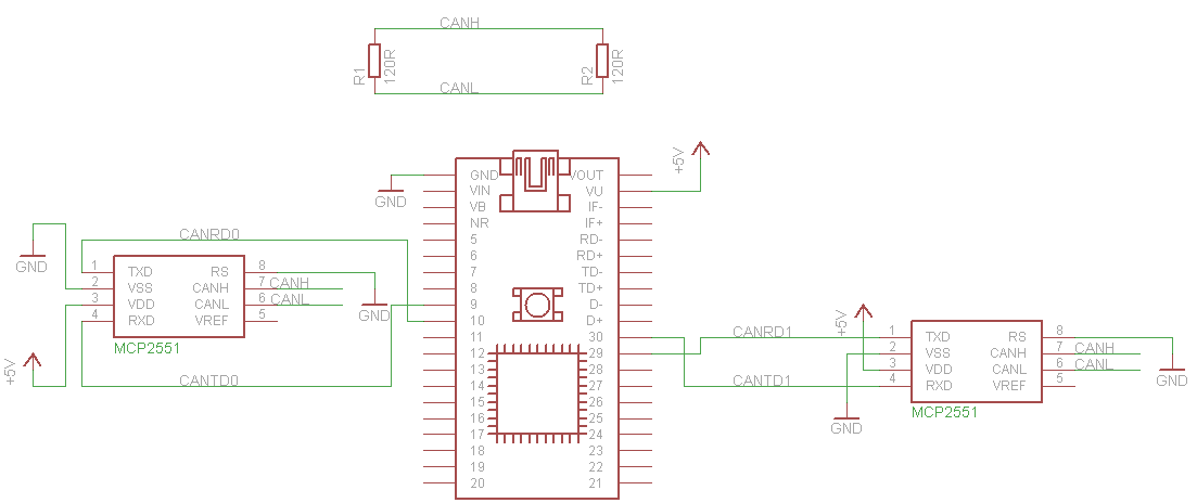
Hi, I am quite net to the mbed and trying to establish communication using CAN. I tried the simple test in the handbook. http://mbed.org/handbook/CAN?compage=2 with the circuitry and code. However, the can2 does not receive the message. because led2 does not light up. Can anyone please help? Also, are the MCP2551 supposed to be powered externally by a 5V source? The circuit diagram also shows a 5V going out of the VU port. What does it power? the transceivers? When I connected the transceivers to an external 5V source, the can1 stops sending after about 2cycles. very confused here. Any help would be appreciated. Thank you

3 Answers
10 years, 2 months ago.
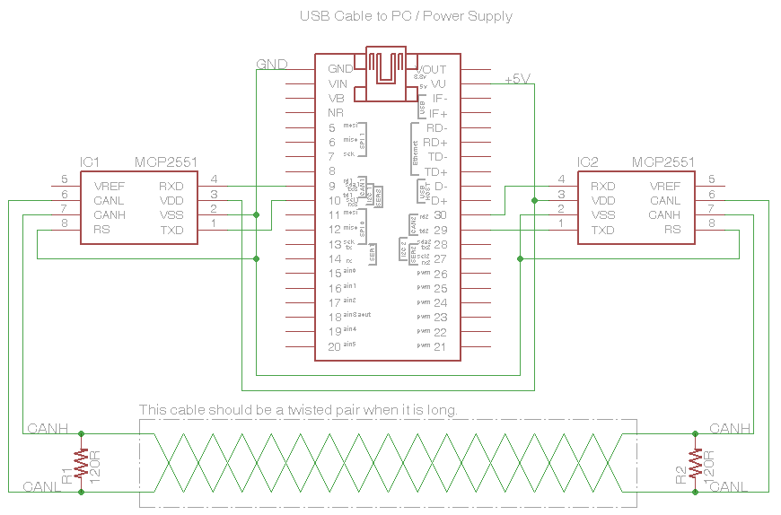
I'm not sure if you're reading the schematic quite right. Even though not "wired" together, each circuit that is identically named (e.g. "+5v") should be electrically connected together. So, both CAN transceivers are connected to the VU pin of the mbed. Similarly, each transceiver and the termination resistors shown at the top have a "CANH" and a "CANL", so these matching names should be connected together.
Here's the same schematic, redrawn -

Thank you David. Will work on it...
Also, I do not totally understand the commands below. Can you please explain?
if(can1.write(CANMessage(1337, &counter, 1))) {
and
ticker.attach(&send, 1);
Is there any connection I need to make so I can view the actual traffic via PC?
Many thanks!
posted by 02 Mar 201410 years, 2 months ago.
I built the same circuit this afternoon. I used VU to power the MCP2551's and it worked. It does not work if you power from 3.3v.
Are you connecting the CANH and CANL signals to each other?
So I power the mbed from via the USB and use the VU pin to power the MCP2551's? Can you please explain how the communication works since there is no physical connection between the two transceivers? Because I would think the flow would be can1 - transceiver1 - transceiver2 - can2.
posted by 02 Mar 2014Yes on the power question.
A physical connection is needed between the two transceivers. You need to connect CANH on transceiver1 to CANH on Transceiver2 and CANL on transceiver1 to CANL on transceiver2. As shown in the diagram directly above the Mbed in the picture above.
Hope this helps.
posted by 02 Mar 201410 years, 2 months ago.
Thanks a lot guys. I missed out the part on the connection between the two transceivers. Will re-do the schematic and update you on the results tomorrow. Also, I do not totally understand the commands below. Can you please explain?
if(can1.write(CANMessage(1337, &counter, 1))) {
and
ticker.attach(&send, 1);
Is there any connection I need to make so I can view the actual traffic via PC?
Many thanks!
In CAN, messages placed on the network have an Identifier, and Data. For CAN on the mbed, you can send from zero to eight bytes of data in a single packet.
Understanding CANMessage is essential to using this well. It accepts up to 5 parameters; those shown in the example below are:
- 1337 - a randomly selected identifier. In the default mode of this message, this is an 11-bit value.
- &counter - starting address of the block of data to send, which happens to point to the only byte being sent.
- 1 - the number of bytes to send at the fore-mentioned address.
can1.write( ) returns true if the message was successfully sent (network good, outbound buffer not full, etc)
#include "mbed.h"

Ticker ticker;
DigitalOut led1(LED1);
DigitalOut led2(LED2);
CAN can1(p9, p10);
CAN can2(p30, p29);
char counter = 0;

void send() {
    printf("send()\n");
    if(can1.write(CANMessage(1337, &counter, 1))) {
        printf("wloop()\n");
        counter++;
        printf("Message sent: %d\n", counter);
    }
    led1 = !led1;
}
And then for a look at the while loop - you see it will [wastefully] print "loop()" and it will [wastefully] wait(0.2), so if you were monitoring a busy network, both of these would be not such a good idea.
But in the middle is the if (can2.read(msg)) which fills in msg and returns true if one has been received. Very likely you will expand on the printf, in order to print the identifier, perhaps the number of bytes of data, and then each byte in that packet.
int main() {
    printf("main()\n");
    ticker.attach(&send, 1);
    CANMessage msg;
    while(1) {
        printf("loop()\n");
        if(can2.read(msg)) {
            printf("Message received: %d\n", msg.data[0]);
            led2 = !led2;
        }
        wait(0.2);
    }
}
Shown in the example, the two ports simply talk to each other. In a more practical application, you may only need one of those CAN ports, which you connect to some other system (e.g. car OBD-II port). When connecting to some other system, you should leave the resistors off the circuit - they will already be present in that other system.
The next very important item when connecting to some other system is to connect at the correct communication bit-rate. Use the can1.frequency( ) api to set the bit-rate.
There is so much more to CAN that there are books on the subject.
posted by 02 Mar 2014Thanks David. I have read the book by Wilfred Voss though it does not go into implementation. From your comment, I can specify my message ID and number of bytes of data but not the actual data? And the command:
printf("Message received: %d\n", msg.data[0]);
prints the message data in address zero which is the 1 byte that was sent? Please correct me if I'm wrong.
Also, I do not understand the function the ticker command plays. Is ticker a sort of timer?
ticker.attach(&send, 1);
posted by 02 Mar 2014When you create a message to send, you can specify the id, data, and the number of bytes (up to 8). You can also specify the format (11 or 29-bit id). See CANMessage for that information.
that printf does only print the single byte - that's standard notation for subscript zero in the array ".data".
ticker is indeed a timer. I haven't used it in a while, you can find it in the mbed library as well - but I think that line indicates it will send a message once per second.
posted by 02 Mar 2014Thanks.
I couldn't lay hands on 120ohm resistors so I used 100ohms but it still didn't work. Can2 still not receiving. Do the resistor values really matter?
posted by 03 Mar 2014Termination: It can handle quite a bit of tolerance - especially at your bench, 1 resistor anywhere from about 50 to a few hundred ohms should be fine. If your CAN cable is up to a few meters you won't need 2 resistors. It will likely work well beyond that, but if it doesn't then circle back to this issue. In a "production" environment, there is typically a defined wire gauge, insulation thickness and twists per inch/cm. In this configuration it is a transmission line, and then the resistance termination is selected to properly match the transmission line and help prevent reflections/echo's of the signal.
For troubleshooting:
- CAN-H connects to CAN-H (make sure not accidentally swapped)
- Check the interconnects to the CAN transceivers, especially power and ground.
- If you have a scope - you can probe TXD on the transceiver and compare that to the signal on CAN-H and CAN-L.
- If you do not have a scope, then don't enable the CAN driver, but instead enable DigitalOut on the mbed pin 10 (that drives the TXD), and set it to toggle slowly. If you have an LED and a current limit resistor (maybe 500 ohms to 1K), you could see the signal pulsing.
- I haven't tried it, but you might then be able to put the LED/Resistor across CAN-H, CAN-L to see it pulse there. The drive voltage is only 2v, but it might work.
- Repeat that test from pin 29.
Thanks David. Will troubleshoot using the scopes...
However, I'm a bit confused on the pin connections. Is it TXD on mbed to TXD on transceiver? or the other way around.
I see that the circuit diagram has TX(mbed) to Rx(transceiver) on can1 but Rx(transceiver) to Rx(mbed) on can2
posted by 04 Mar 2014Thanks a lot David, I've been able to get it working. However, how do I view the data transferred on a PC?
posted by 04 Mar 2014Hi
if(can1.write(CANMessage(1337, &counter, 1)))
I am still a bit confused about this statement especially the " &counter " expression. Is it that the CAN Message data has to be the address of the data not the actual data itself? I am a bit confused because I get an error when trying to use that line of code to send temperature sensor readings over CAN. Any help will be appreciated.
posted by 20 Jun 2014
if(can1.write(CANMessage(1337, &counter, 1)))
I am still a bit confused about this statement especially the " &counter " expression. Is it that the CAN Message data has to be the address of the data not the actual data itself?
posted by UniLeedsElec28 UniLeedsElec28 20 Jun 2014