Important changes to forums and questions
All forums and questions are now archived. To start a new conversation or read the latest updates go to forums.mbed.com.
12 years, 3 months ago.
LPC 1768 PIN Layout & GPIO
Hi!
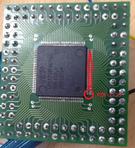
can someone confirm my assumption to PIN 1 (up to 25)?

Furthermore I have tried to connect 3.3 V to PIN 28 (VDD) and ground to PIN 32 (VSS) to run an LED on PIN 32 (GPIO) but that did not work (but I was hoping that it works)
Does anyone have an idea why it does not work?
Thanks Florian
2 Answers
12 years, 3 months ago.
See: http://mbed.org/forum/mbed/topic/2309/. So I think you got it correct (makes no sense tbh with writing, but blame NXP for that).
Regarding your other problem, how did you program it, and did that go correctly?
12 years, 3 months ago.
Thanks for your confirmation!
I have not programmed anything. I was hoping 3.3 V and ground are enough to power up the GPIO-output to connect a LED to PIN 32. As far as I understand der LPC1768 user manual (page 120) GPIO output should enabled/powerd up by default.
http://www.nxp.com/documents/user_manual/UM10360.pdf
The GPIOs are not powered down, like other peripherals can be. But that doesn't me they are logic '1' by default. They are by default pull-up iirc. But I just checked the LEDs on my own LPC1768 mbed board, and the LEDs are VERY faint.
And that is their default state, but while I am not sure, I wouldn't be surprised if that requires a reset and possibly also an active clock signal to get there.
posted by 05 Nov 2013
You have a short on pins 89 & 90, possibly 36-38 as well looking at the photo !
I have a post (somewhere) with the minimum requirements, to get device running, you need at least 2 caps, for power, 12MHz crystal & 2 * 18pF caps,
reset & ISP circuit,
and of course ISP programming lead, or JTAG.
have a look at My minimal
posted by ceri clatworthy 06 Nov 2013