Important changes to forums and questions
All forums and questions are now archived. To start a new conversation or read the latest updates go to forums.mbed.com.
12 years, 7 months ago.
How to Delay SPI Slave to Master Response?
I am trying to have two mbed talking to each other. One setup as SPI master and one setup as SPI Slave. This code from from the SPI section with slight modification. When I compile and run the codes, I should expect 0xAA but I am not getting the correct value. Any idea what did I do wrong here?
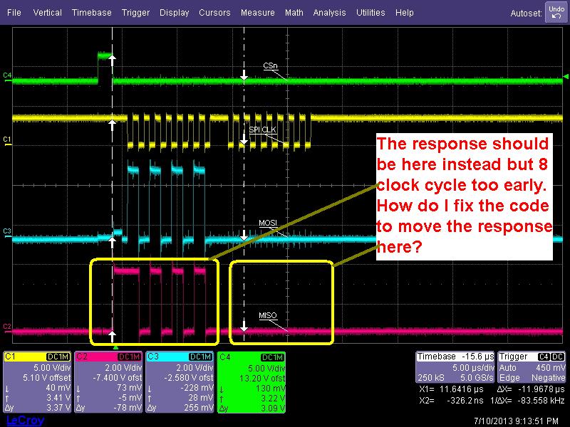
I scope out the signal. The Slave responded too early. How do I delay it for 8 clock cycle later. I tried the wait statement but it doesn't work.

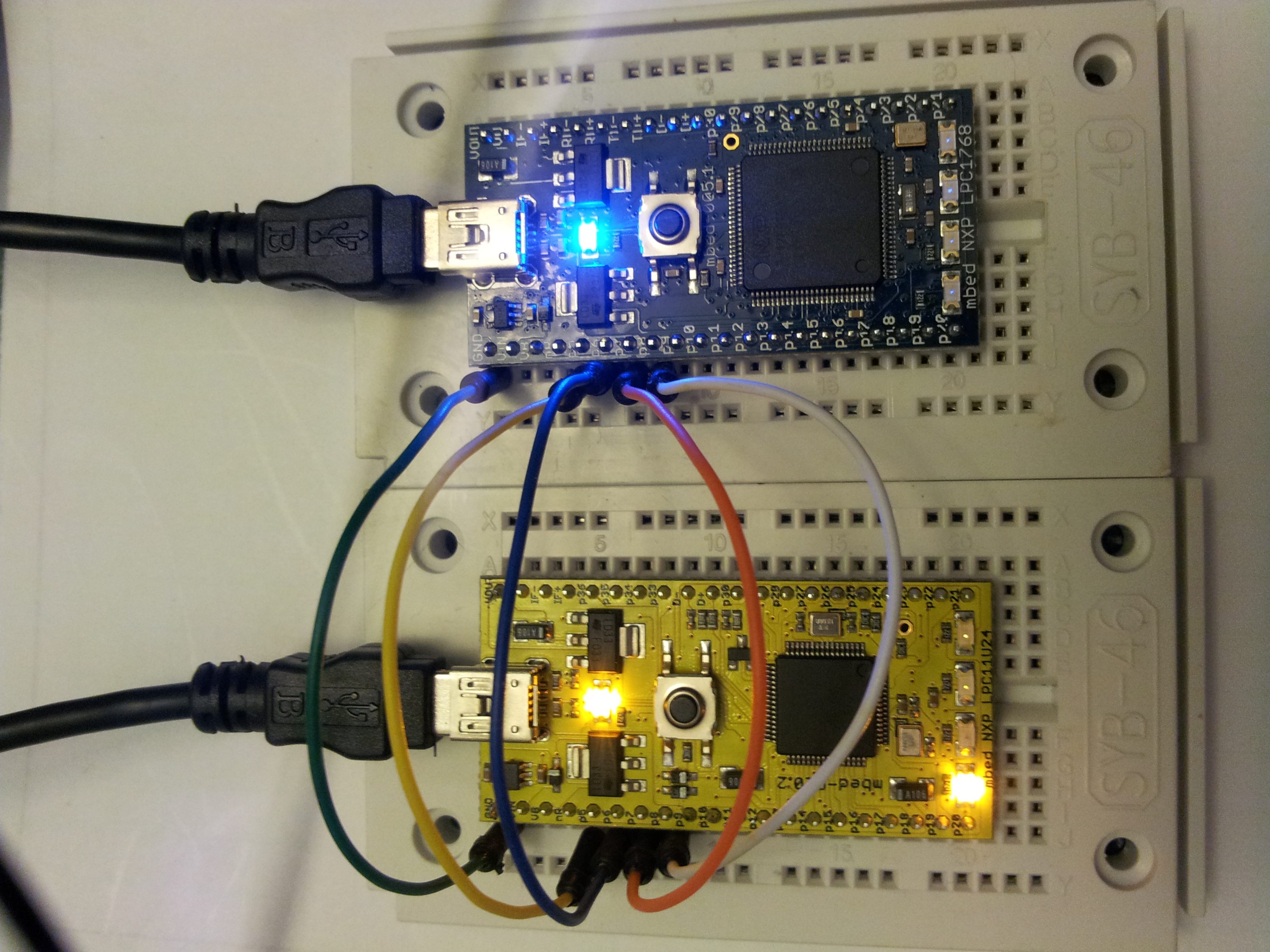
Here is the picture of the two and the connection in between: 
SPI Master Code
//Here is my connection
//MBED1                 MBED2
//SPI Master            SPI slave
//P5 ------------------- p5
//p6 ------------------- p6
//P7 ------------------- p7
//p8 ------------------- p8
//GND ----------------GND


#include "mbed.h"

SPI spi(p5, p6, p7); // mosi, miso, sclk
DigitalOut cs(p8);
Serial pc(USBTX, USBRX);

int main() {
    // Chip must be deselected

        // Setup the spi for 8 bit data, high steady state clock,
    // second edge capture, with a 1MHz clock rate
    spi.format(8,3);
    spi.frequency(1000000);

    while (1) {
    cs = 1;
    // Select the device by seting chip select low
    cs = 0;

    // Send 0x8f, the command to read the WHOAMI register
    spi.write(0xAA);

    // Send a dummy byte to receive the contents of the WHOAMI register
    int whoami1 = spi.write(0x00);
    pc.printf("WHOAMI register = 0x%X\n\r", whoami1);

    // Deselect the device
    cs = 1;
    wait_us (1);  // debug stall period
    }
}
SPI Slave Code
 // Reply to a SPI master as slave

 // Slave's Response.

#include "mbed.h"
#include <SPISlave.h>

SPISlave device(p5, p6, p7, p8); // mosi, miso, sclk, ssel


 int main() {
     int v;
     device.reply(0x00);              // Prime SPI with first reply
     while(1) {

         if(device.receive()) {
             v = device.read();   // Read byte from master
             device.reply(v);         // Make this the next reply
         }
     }
 }
5 Answers
11 years, 8 months ago.
I did the following modifications:
SPI Master
int main() {
     // Setup the spi for 8 bit data, high steady state clock,
    // second edge capture, with a 1MHz clock rate
    spi.format(8,3);
    spi.frequency(1000000);

    while (1) {
    // Deselect the device
    cs = 1;
    // Select the device by seting chip select low
    cs = 0;

    // Send 0xAA, the command to read the WHOAMI register
    spi.write(0xAA);

    // Deselect the device
    cs = 1;
    wait_us (1); // debug stall period

    // Select the device by seting chip select low
    cs = 0;

    // Send a dummy byte to receive the contents of the WHOAMI register
    int whoami1 = spi.write(0x02);
    pc.printf("WHOAMI register = 0x%X\n\r", whoami1);

    // Deselect the device
    cs = 1;
    wait_us (1);  // debug stall period
    }
}
SPi Slave
 int main() {
     int v;
     device.reply(0x00);              // Prime SPI with first reply
     while(1) {

         if(device.receive()) {
             v = device.read();   // Read byte from master
             if (v==0xAA) {         //Verify the command
                 v = device.read();  // Read byte from master
                 device.reply(v);         // Make this the next reply
                 }
             else{
                 device.reply(0x00);  //Reply default value
                     }
         }
     }
 }
The connections are good, (MOSI: Master Output, Slave Input; and MISO: Master Input, Slave Output). I did tests changing the command 0xAA of the code of SPI Master to receive a different response. This code is working. Try to run these modifications in the original code of this post. Thank you.
posted by 21 May 201411 years, 8 months ago.
On your hard-wired connections: Master mosi p5 must connect to Slave miso p6 Slave mosi p5 must connect to Master miso p6
As you have it wired now, MasterOutSlaveIn is incorrectly tied to MasterOutSlaveIn. These connection must cross-over in order to communicate back-and-forth. You are not reading the the slave miso response, but the same mosi signal you are sending out. Regards, Dave
8 years, 6 months ago.
Slave communication is shifted by one byte. To respond for ex for a START byte, you need to put the ACK byte prepared on the bus even before having the START byte received by the slave. As the Master write the SPI bus the START Command, the prepared byte on the slave SPI bus will be transferred to the Master immediately. So, you need to prepare the SPISlave device to shift the bytes by one byte as in the following example.
The NUCLEO-F030R8 is master against a BME280 SPI device, but the NUCLEO-F030R8 is a slave against another NUCLEO-L476RD device and they communicate as follow: Master device ask the slave device to provide temp,hum,pres from the BME280. Slave collect the information from BME280 and send it to the master.
main(){
   slave.format(8,0);
    slave.frequency(1000000);
    slave.reply(SPI_ACK);       //You need to prepare the ACK answer and put it on the bus
    DEBUG_MESSAGE("Testing is started from slave side\n");
    //TODO: PULL UP RESISTOR TO THE CS .. TRY TO TEST IT .. I AM NOT SURE IF THAT REQUIRED.
    res =0;
    int vs;
     while(1) {
        if(slave.receive()) {
              vs=slave.read();
            switch(vs) {
                case SPI_START: {
                    DEBUG_MESSAGE("-----------------------------\n");
                    PacketToBeSend(0);
                    d=sensor.getTemperature()/100;
                    c=sensor.getPressure()/100;
                    e=sensor.getHumidity();

                    break;
                }
                case 0:PacketToBeSend(1);break;
                case 1:PacketToBeSend(2);break;
                case 2:slave.reply(SPI_ACK);break;
                default:{DEBUG_MESSAGE("ERROR ..... %d\n",vs);}
            }
        }

    }
12 years, 7 months ago.
I am just trying to get two mbed talking thru SPI but somehow the master doesn't read the correct value. Not sure why? Perhaps I can scope the signal?
12 years, 7 months ago.
The microcontroller on an mbed requires you to raise CS between every byte. Not sure how you get your 0x13, but that is something I would try first.