Important changes to forums and questions
All forums and questions are now archived. To start a new conversation or read the latest updates go to forums.mbed.com.
12 years, 10 months ago.
making LCD 16x2 work
Im using HBD44780 LCD 16x2 and able to power on the LCD backlight. but does not display the text when running code below.
 #include "mbed.h"
 #include "TextLCD.h"

  TextLCD lcd(p15, p16, p17, p18, p19, p20); // rs, e, d4-d7 but could use 27,28,29,30 instead of 17,18,19,20

  int main() {
      lcd.printf("Hello World!\n");
  }
how can i troubleshoot this?
and i was also kinda wondering why R/W is not being used anymore in the parameters.
1 Answer
12 years, 10 months ago.
R/W needs to be connected to GND rather than to an mbed pin. The library does not read back from the display. This is quite common practice. The only real reason to read back from the display is to check the busy flag. You can avoid that by just waiting for the appropriate time.
You can find some more hints on my cookbook page for an enhanced LCD library: https://mbed.org/cookbook/Text-LCD-Enhanced
hi wim, please do consider that im just starting to learn all these things so some terms are quite hard to understand. "the library does not read back from the display" i really dont get what you mean by this quite honestly, can you kindly elaborate more.
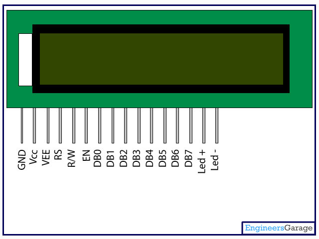
based on the manual that came with the LCD, im using exactly like this http://www.engineersgarage.com/sites/default/files/Lcd_0.jpg
as a newbie, im just so excited to just simply print a "hello world" on my LCD.
posted by 04 Jul 2013The "Read-notWrite" (R/W) pin selects whether the microcontroller is writing data or commands to the display or reading from the display. R/W must be at logic low level or Ground (GND) for writing and R/W must be at logic high level (3.3V for mbed) for read operations. This particular mbed library for LCDs does not readback any data from the display. All interactions with the LCD are write operations. So the mbed does not need to change the logic level on the R/W pin. In fact the pin is not even connected to the mbed. However, the LCDs R/W pin does need to be at a defined level to make sure the LCD knows that you are writing to it. Therefor the R/W pin should always be at GND level. The databus pins (d4-d7) and the RS and E pin need to be controlled by the mbed through the LCD library and should be connected to the correct pins as identified in the parameter list of TextLCD:
TextLCD lcd(p15, p16, p17, p18, p19, p20); // rs, e, d4-d7 but could use 27,28,29,30 instead of 17,18,19,20
The TextLCD library software will drive all the LCD pins as needed when you call one of its methods like 'printf'.
Make sure that you have connected the RS, E, DB4-DB7 pins to the correct mbed pins Also make sure that: - LCD GND and LCD R/W pins are connected to mbed GND (pin 1), - LCD VCC is connected to mbed 3.3V out (pin 40) or 5V (pin 39). Generally 5V is better, depends on your LCD - LCD VEE is connected to a variable resistor that provides a voltage between 0V and a small positive voltage. Easiest way is to use a potmeter with one end at GND, other end at 3.3V and runner at LCD VEE. The VEE voltage can be used to adjust contrast.
A schematic is shown on the LCD cookbook page.
posted by 04 Jul 2013