Important changes to forums and questions
All forums and questions are now archived. To start a new conversation or read the latest updates go to forums.mbed.com.
12 years, 8 months ago.
[Solved] SPI with MCP DigiPOT !!
Im trying to connect a digital pot >> http://dlnmh9ip6v2uc.cloudfront.net/datasheets/Components/General%20IC/22060b.pdf to a KL25z ,
#include "mbed.h"

DigitalOut CS(PTA17);
SPI spi(PTD2, PTD3, PTD1);
int value;
int main() {
    // Setup the spi for 8 bit data, high steady state clock,
    // second edge capture, with a 1MHz clock rate
    spi.format(7,3);
    spi.frequency(1000000);

    while(1) {
        //basically just ramp the wiper up and down the full range
    //but the upwards ramp is deliberately faster than the downwards ramp

    for (int level = 0; level <= 127; level++)
    {
      //take the SS pin low to select the chip:
      CS = 0x00;
      //send in the address and value via SPI:
      spi.write(0);
      spi.write(level);
      // take the SS pin high to de-select the chip:
      CS = 0xFF;
      //increase this number to slow things down
      //(10000) is a good number if you want to see the LED pulsing nicely
      wait_us(100);
    }

    for (int level = 127; level >= 0; level--)
    {
     //take the SS pin low to select the chip:
      CS = 0x00;
      //send in the address and value via SPI:
      spi.write(0);
      spi.write(level);
      // take the SS pin high to de-select the chip:
      CS = 0xFF;
      //increase this number to slow things down
      //(20000) is a good number if you want to see the LED pulsing nicely
      wait_us(200);
    }

   }

}
but nothing happens
3 Answers
12 years, 8 months ago.
There is something wrong in the SPI setup. You select 7 databits...
// Setup the spi for 8 bit data, high steady state clock,
    // second edge capture, with a 1MHz clock rate
    spi.format(7,3);
    spi.frequency(1000000);
SPI should be setup for 8 bits
spi.format(8,3);
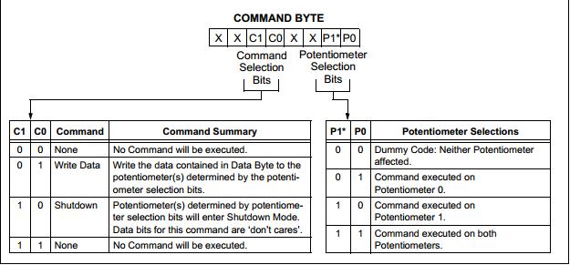
You probably also need to send a command (non zero) before sending the wiper value.
I have tried setting commands as enlisted in the datasheet who's link I posted on the very first post , 7 bits used here because the pot is addressable using 7 bits also
posted by 14 May 2013Depending on the device it seems to accept 7 bit values for the wiper, but the datatransfer should be either 8 or 16 bits. Most SPI devices ignore all data if it does not comply with the expected format.
A quick look at table 7-2 shows that an 8 bit command to increment wiper_0 is '0000 0100'. The full 16 bit command to set the wiper_0 to a certain level is '0000 00nn nnnn nnnn' where nnn is the level using 7 significant bits.
posted by 14 May 2013It worked Still keeping the command spi.write(0); BUT changing the format(8,3);
posted by 14 May 2013Good. You are now sending the 16 bit command '0000 00nn nnnn nnnn' as two parts of 8 bits each: '0000 0000' + '0nnn nnnn' with 7 significants bits for the level nnn nnnn.
posted by 14 May 201312 years, 8 months ago.
Hi,
I dont know which MCP you are using. I have given a command for the MCP41050.

Like this, i think your MCP also should have been written a command before data.
I mean, spi.write(0) - Instead of 0 the command should be placed.
Hope this helps.
Murugesh
12 years, 8 months ago.
But as per the comment below in this page its working! http://www.uduino.com/tutorials/1