AdBun-M4NR development board
AdBun-M4NR development board for Toshiba TMPM4NRF20FG MCU.

Overview
The TMPM4NRF20FG is ARM® Cortex®-M4 based microcontroller. TMPM4NRF20FG have Ethernet Controller with data transfer rate of 100 Mbps over Ethernet in compliance with IEEE 802.3-2008 standards.This product has peripheral functions which are suitable for motor and inverter control as AD Converter (ADC), Motor control circuit (A-PMD). This product ideally suited to applications in Internet of Things (IoT) devices, energy management systems, sensor technology, and industrial equipment. This product has compatible function with existing products and attain low current consumption. This microcontroller can be widely used for home appliances and industrial equipment. Based on an ARM Cortex-M4 core, with a maximum operating frequency of 200 MHz, the TMPM4NRF20FG incorporates 2048 Kbyte of flash memory and 256 Kbyte SRAM required for secure communications control and backup RAM of 2 Kbyte.
TMPM4NR Features
- TMPM4NRF20FG in LQFP176 package
- ARM®32-bit Cortex®-M4 CPU, 200 MHz max CPU frequency
- 256KB RAM
- 2048KB Flash
- TSPI (2)
- I2C (4)
- UART (6)
- PWM (13)
- 12bit ADC (17)
- A-PMD(1)
- GPIO (146)
AdBun-M4NR Feature
- Compatible with a wide range of commercially available shields
- 2 Push Switch
- 4 DIP Switch
- 4 LED
- Built-in USB drag 'n' drop FLASH programmer
Pin Layout
CN202 Pin Header

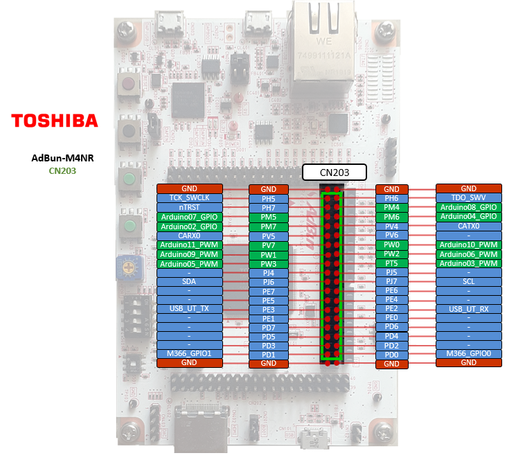
CN203 Pin Header

CN204 Pin Header

CN205 Pin Header

Arduino Pin Header

| PWM Pins | UART Pins | I2C Pins | LED Pins | Switch Pins | ||||
|---|---|---|---|---|---|---|---|---|
| PW1 | MBEDIF_TXD = PV1 | SDA = PF2 | LED1 = PW4 | SW1 = PL5 | ||||
| PW2 | MBEDIF_RXD = PV0 | SCL = PF3 | LED2 = PW5 | SW2 = PV2 | ||||
| PT3 | LED3 = PW6 | |||||||
| PD2 | LED4 = PW7 | |||||||
| PD4 | ||||||||
| PE1 | ||||||||
| PE6 | ||||||||
| PL4 | ||||||||
| PL6 | ||||||||
| PC4 | ||||||||
| PW6 | ||||||||
| PU0 | ||||||||
| PU6 |
| Arduino I/O Pins | Arduino Analog Pins | Arduino PWM Pins | ||
|---|---|---|---|---|
| D0 = PJ1 | A0 = PN0 | D9 | ||
| D1 = PJ0 | A1 = PN1 | |||
| D2 = PM7 | A2 = PN2 | |||
| D3 = PT5 | A3 = PN3 | |||
| D4 = PM6 | A4 = PN4 | |||
| D5 = PW3 | A5 = PN5 | |||
| D6 = PW2 | ||||
| D7 = PM5 | ||||
| D8 = PM4 | ||||
| D9 = PW1 | ||||
| D10 = PA7 | ||||
| D11 = PA4 | ||||
| D12 = PA5 | ||||
| D13 = PA6 | ||||
| D14 = PF2 | ||||
| D15 = PF3 |
| General Purpose Input / Output |
|---|
| PA0, PA1, PA2, PA3, PA4, PA5, PA6, PA7 |
| PB0, PB1, PB2, PB3 |
| PC4, PC5, PC6, PC7 |
| PD0, PD1, PD2, PD3, PD4, PD5, PD6, PD7 |
| PE0, PE1, PE2, PE3, PE4, PE5, PE6, PE7 |
| PF0, PF1, PF2, PF3, PF4, PF5, PF6, PF7 |
| PG0, PG1, PG2, PG3, PG4, PG5, PG6, PG7 |
| PH0, PH1, PH2, PH3, PH4, PH5, PH6, PH7 |
| PJ0, PJ1, PJ2, PJ3, PJ4, PJ5, PJ6, PJ7 |
| PK0, PK1, PK2, PK3, PK4, PK5, PK6, PK7 |
| PL0, PL1, PL2, PL3, PL4, PL5, PL6, PL7 |
| PM0, PM1, PM2, PM3, PM4, PM5, PM6, PM7 |
| PN0, PN1, PN2, PN3, PN4, PN5, PN6, PN7 |
| PP0, PP1, PP2, PP3, PP4, PP5, PP6, PP7 |
| PR0, PR1, PR2, PR3, PR4, PR5, PR6, PR7 |
| PT0, PT1, PT2, PT3, PT4, PT5 |
| PU0, PU2, PU3, PU4, PU5, PU6, PU7 |
| PV0, PV1, PV2, PV3, PV4, PV5, PV6, PV7 |
| PW0, PW1, PW2, PW3, PW4, PW5, PW6, PW7 |
| PY0, PY1, PY2, PY3, PY4 |
Technical Reference
Schematics
Data Sheet
Interface Firmware (I/F)
Please update the interface firmware in the following way when upgrading, or if it has been deleted for some reasons.
- Download Flash programmer that programming tool to program I/F firmware.
When you use the flash programmer, you need to agree "SOFTWARE LICENSE AGREEMENT"
Download Flash Programmer
Download AdBun-M4NR Firmware
To update I/F firmware, old firmware needs to be erased before updating the firmware.
Mandatory On Board Jumper Settings
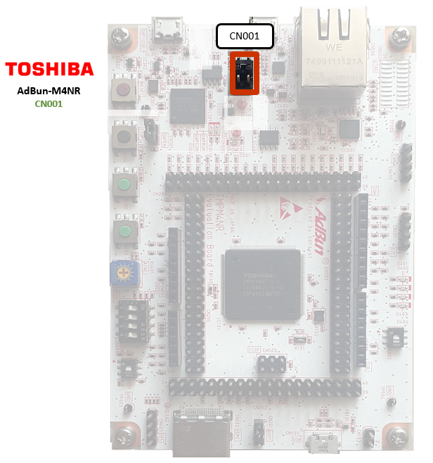
- Short pins 3,4 of CN001 to supply power to board

- Short CN301 to enable DAP

How to erase and program I/F firmware
- Short CN302

- Connect PC to DAP(USB) on AdBun-M4NR by micro USB cable

- Start up Flash Programmer
Click FlashProgIT.exe on your PC. - Select [Device] tab
- Select Series "TX03 Series"
- Select Device "TMPM366FY" and push Apply button on Device tab.
- Select [Object File] tab and browse the downloaded AdBun-M4NR Firmware
- Select "USB" at Communication tab and push OK button.
- Select [Edit]-[Chip Erase] from the menu bar.
(If you meet password error, select [Setup] -[ Password] from the menu bar and select "Device is Blank" )
(If you meet command error, reconnect USB cable and try [Edit]-[Chip Erase] again
- Once erase is completed, Select [Edit] - [Erase/Program] from the menu bar.
(If you meet password error, select [Setup] -[ Password] from the menu bar and select "Device is Blank" )
(If you meet command error, reconnect USB cable and try [Edit]-[Erase/Program] again
- Remove jumper on CN302
- Reconnect USB cable
DAPLink drive will appear if I/F firmware is programmed successfully
Known issues
Warning
The latest version of "mbedls" is not able to detect the board.
The workaround is to mock the detection of the board:
mbedls --mock 7022:TMPM4NR
You need to log in to post a discussion
