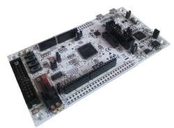
SBK-M4KN development board
SBK-M4KN development board for Toshiba TMPM4KNFYAFG MCU.
Overview
The TMPM4KNFYAFG is ARM® Cortex®-M4 based microcontroller. TMPM4KNFYAFG have peripheral functions which are suitable for motor and inverter control as AD Converter (ADC), Motor control circuit (A-PMD), Vector Engine (A-VE+), and Encoder input (A-ENC). This product has compatible function with existing products and attain low current consumption. This microcontroller can be widely used for home appliances and industrial equipment.
Based on an ARM Cortex-M4 core, with a maximum operating frequency of 160 MHz, the TMPM4KNFYAFG incorporates 256 Kbyte of flash memory and 24 Kbyte SRAM required for secure communications control.
TMPM4KN Features
- TMPM4KNFYAFG in LQFP100 package
- ARM®32-bit Cortex®-M4 CPU, 160 MHz max CPU frequency
- 24KB RAM
- 256KB Flash
- TSPI (2)
- I2C (1)
- UART (4)
- PWM (4)
- 12bit ADC (11)
- A-PMD(3)
- A-VE+(1)
- GPIO (87)
SBK-M4KN Feature
- Compatible with a wide range of commercially available shields
- Power option
- USB-UART
- DAP-USB
- 4 Push Switch
- 6 LED
- 1 Variable resistor
- Built-in USB drag 'n' drop FLASH programmer
Pin Layout
J9 Pin Header

J10 Pin Header

Arduino Pin Header

| PWM Pins | UART Pins | I2C Pins | LED Pins | Switch Pins | ||||
|---|---|---|---|---|---|---|---|---|
| PF4 | CONSOLE_TX = PC0 | SDA = PD3 | LED1 = PB0 | SW1 = PG3 | ||||
| PU2 | CONSOLE_RX= PC1 | SCL = PD4 | LED2 = PB2 | SW2 = PG4 | ||||
| PC2 | LED3 = PB4 | SW3 = PG5 | ||||||
| PN1 | LED4 = PV0 | SW4 = PG6 | ||||||
| LED5 = PV1 | ||||||||
| LED6 = PB6 |
| Arduino I/O Pins | Arduino Analog Pins | Arduino PWM Pins | ||
|---|---|---|---|---|
| D0 = PF7 | A0 = PM2 | - | ||
| D1 = PF6 | A1 = PM1 | |||
| D2 = PD4 | A2 = PM0 | |||
| D3 = PD5 | A3 = PL3 | |||
| D4 = PC6 | A4 = PL1 | |||
| D5 = PC7 | A5 = NC | |||
| D6 = PA0 | ||||
| D7 = PC3 | ||||
| D8 = PD0 | ||||
| D9 = PD1 | ||||
| D10 = PG1 | ||||
| D11 = PG5 | ||||
| D12 = PG4 | ||||
| D13 = PG6 | ||||
| D14 = PC0 | ||||
| D15 = PC1 |
| General Purpose Input / Output |
|---|
| PA0, PA1, PA2, PA3, PA4 |
| PB0, PB1, PB2, PB3, PB4, PB5, PB6, PB7 |
| PC0, PC1, PC2, PC3, PC4, PC5, PC6, PC7 |
| PD0, PD1, PD2, PD3, PD4, PD5 |
| PE0, PE1, PE2, PE3, PE4, PE5, PE6, PE7 |
| PF0, PF1, PF2, PF3, PF4, PF5, PF6, PF7 |
| PG0, PG1, PG2, PG3, PG4, PG5, PG6 |
| PH0, PH1 |
| PJ0, PJ1, PJ2, PJ3, PJ4, PJ5 |
| PK0, PK1, PK2, PK3, PK4 |
| PL0, PL1, PL2, PL3, PL4, PL5, PL6, PL7 |
| PM0, PM1, PM2 |
| PN0, PN1, PN2 |
| PU0, PU1, PU2, PU3, PU4, PU5, PU6, PU7 |
| PV0, PV1 |
On Board UART Usage Setting
To use DAP-UART it is necessary to move switch SW5 to position "MBD". To use USB-UART, move switch SW5 to position "USB"

Technical Reference
Schematics
Data Sheet
Interface Firmware (I/F)
Please update the interface firmware in the following way when upgrading, or if it has been deleted for some reasons.
- Download Flash programmer tool Flash Programmer_M366_202112.zip to program I/F firmware.
- Download ESP-SBK-M4KN I/F Firmware tmpm366_tmpm4kn_stk_firmware_v0254.hex
To update I/F firmware, old firmware needs to be erased before updating the firmware.
Mandatory On Board Jumper Settings
- Short JP6 to supply power to board

- Short JP1 to enable DAP and short JP4 to enable SWD

How to erase and program I/F firmware
- Short JP2

- Connect PC to USB1 on SBK-M4KN by micro USB cable

- Start up Flash Programmer
Click FlashProgIT.exe on your PC.
When you use the flash programmer, you need to agree "SOFTWARE LICENSE AGREEMENT"
- Select [Device] tab
- Select Series "TX03 Series"
- Select Device "TMPM366FY" and push Apply button on Device tab.
- Select [Object File] tab and browse the downloaded ESP-SBK-M4KN Firmware
- Select "USB" at Communication tab and push OK button.
- Select [Edit]-[Chip Erase] from the menu bar.
(If you meet password error, select [Setup] -[ Password] from the menu bar and select "Device is Blank" )
(If you meet command error, reconnect USB cable and try [Edit]-[Chip Erase] again
- Once erase is completed, Select [Edit] - [Erase/Program] from the menu bar.
(If you meet password error, select [Setup] -[ Password] from the menu bar and select "Device is Blank" )
(If you meet command error, reconnect USB cable and try [Edit]-[Erase/Program] again
- Remove jumper on JP2
- Reconnect USB cable
DAPLink drive will appear if I/F firmware is programmed successfully
Known issues
Warning
The latest version of "mbedls" is not able to detect the board.
The workaround is to mock the detection of the board:
mbedls --mock 7020:TMPM4KN
You need to log in to post a discussion
To compile a program for this board using Mbed CLI, use TMPM4KN as the target name.
Board Partner
Toshiba
Toshiba Corporation, a Fortune Global 500 company, channels world-class capabilities in advanced electronic and electrical product and systems into three focus business fields: Energy that sustains everyday life, that is cleaner and safer; Infrastructure that sustains quality of life; and Storage that sustains the advanced information society.
Mbed OS support
- Mbed OS 6.15