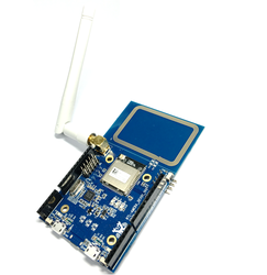
Realtek RTL8195AM
Ameba is an Arduino-compatible development board for internet of things, beside WiFi connectivity, it also includes an NFC tag, and can support Ethernet via Arduino compatible headers. The brain of the board is Realtek RTL8195AM Wi-Fi SoC with Arm®Cortex®-M3 MCU inside that includes WiFi connectivity, hardware SSL, SRAM, and flash. It provides the optimal solution for the maker community and Quadcopter, Solar Energy system, Sensor Environment, automation solutions and etc.
Highlights
- 32-bit Arm®Cortex®-M3, up to 166MHz
- 1MB ROM, 2MB SDRAM and 512KB SRAM
Key Features
- Integrated with 802.11 b/g/n 1x1 Wi-Fi
- NFC Tag with Read/Write Function
- 10/100 Ethernet MII/ RMII/RGMII Interface
- USB OTG
- SDIO Device/SD card controller
- Hardware SSL engine
- Maximum 30 GPIOs
- 2 SPI Interfaces and support both master and slave mode
- 3 UART Interfaces including 2 HS-UART and one log UART
- 4 I2C Interfaces and support both master and slave mode
- 2 I2S/PCM Interfaces and support both master and slave mode
- 4 PWM interfaces
- 2 ADC interfaces
- 1 DAC interfaces
Connector Information
In order to be able to connect to the Ameba board and flash code, the micro usb connector needs to be connected to the port marked as "CON2". The below image can be referred for better clarity.

Pin Layout
The Arduino Compatible Pins
The image below shows the arduino compatible pins on the ameba board.

RTL8195AM pinout (left)

Warning
Both A0 and A1 are connected to ADC_CH1
A0, A1, A2 and DAC are not capable for GPIO
All the LED's on the board are used by the CMSIS-DAP and are not programmable by user, in order to test LED, please connect external LED
There are 3 buttons on the board, the two buttons near the USB connectors are connected to the DAP and the button on the side is the reset button, there are no user programmable buttons on the platform.
RTL8195AM pinout (right)

Board schematics
Electrical schematics of the Ameba board is found here in User Manual (login required)
The schematics below shows how to setup antenna of Ameba among three choices. 
Example Code
* Example to connect RTL8195AM to MBED cloud(NEW)
* Blinky example
* Wifi example
* Example to connect button to RTL8195AM
Technical Resources
DAPLink Firmware Update
* How to update DAP firmware
* DAP firmware download link[v244] (login required)
After successfully update to DAP firmware that support Mbed, you could verify with "mbedls" command. For example:
>mbedls
+-------------------+----------------------+-------------+-------------+--------------------------------------------------+-----------------+
| platform_name     | platform_name_unique | mount_point | serial_port | target_id                                        | daplink_version |
+-------------------+----------------------+-------------+-------------+--------------------------------------------------+-----------------+
| REALTEK_RTL8195AM | REALTEK_RTL8195AM[0] | E:          | COM24       | 4600000002b7ec8d00000000000000000000000097969902 | 0244            |
+-------------------+----------------------+-------------+-------------+--------------------------------------------------+-----------------+
Articles
* Get Started
* Q & A
See also
* Ameba Offical Website
* Realtek Offical Website

To compile a program for this board using Mbed CLI, use realtek_rtl8195am as the target name.
Board Partner

Realtek
Realtek is a world-leading IC provider that designs and develops a wide range of IC products for communications network, computer peripheral, and multimedia applications.
 Mbed Enabled
- Baseline
Mbed OS support
- Mbed OS 5.10
- Mbed OS 5.11
- Mbed OS 5.12
- Mbed OS 5.4
- Mbed OS 5.5
- Mbed OS 5.6
- Mbed OS 5.7
- Mbed OS 5.8
- Mbed OS 5.9
Example programs