IMXRT1050-EVKB
The i.MX RT1050 is a crossover device with a 600 MHz Cortex-M7 with an i.MX-style architecture.
Overview
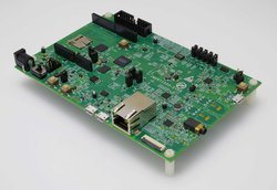
The IMXRT1050-EVKB has been designed by NXP in collaboration with Arm Mbed for prototyping all sorts of devices, especially those requiring high performance, lowest power consumption and price point.
The i.MX RT1050 crossover processor features an ARM® Cortex®-M7 core running up to 600MHz and up to 512KB on-chip RAM. It is supprted by the IMXRT1050-EVKB development board which includes, but is not limited to: SDRAM, Hyper Flash, QSPI Flash, TF card slot, dual-role USB interfaces, Audio CODEC and headers for use with LCD display, CMOS sensor, Ethernet/CAN communication, Bluetooth® and 2.4 GHz radio add-on modules. It is packaged as a development board including extension headers compatible with Arduino R3 shields and includes a built-in USB Debug and Flash Programmer.
The i.MX RT1050 applications processor is ideal for industrial HMI, IoT, motor control and home appliances applications.
Important Notes
Support for the following features of MIMXRT1050-EVK are currently in development in Mbed OS. Schedule for release is TBD.
- USB
Signal Connection Information:
- The I2C signals connected to D14 & D15 on the Arduino header are not capable of I2C Master mode. To use the I2C master mode with an Arduino-compatible shield slave such as a memory shield, connect D14 (SDA) to A4 and D15 (SCL) to A5, and select A4 as I2C_SDA and A5 as I2C_SCL in the code.
- The SPI signals are not connected on the Arduino header by default. To connect the SPI signals, add a 0 ohm resistor to R278, R279, R280 , R281 on the back side of the REVB board.
MCU Features
- Single ARM Cortex-M7 with:
- 32 KB L1 Instruction Cache
- 32 KB L1 Data Cache
- Single-precision and double-precision FPU (Floating Point Unit)
- On Chip Memory:
- Boot ROM (96KB)
- On-chip RAM, configurable RAM up to 512KB shared with M7 TCM
- Security:
- High Assurance Boot (HAB)
- Data Co-Processor (DCP)
- Bus Encryption Engine
- True Random Number Generator
- Secure Non-volatile Storage
- Secure JTAG Controller
- External Memory Interfaces:
- 8/16-bit SDRAM, up to SDRAM-166
- 8-bit SLC NAND FLASH, with ECC handled in SW
- SD/eMMC
- Single/Dual channel Quad SPI FLASH with XIP support
- Parallel NOR FLASH with XIP support
- Graphics:
- Generic 2D Graphics engine
- Flexible image composition options – alpha, chroma key
- Multiple pixel format support (RGB, YUV444, YUV422, YUV420, YUV400)
- Color space conversion
- Display Interface:
- Parallel RGB LCD interface, supporting 8/16/24 bit interface and upto WXGA resolution
- Smart LCD Display with 8/16-bit MPU/8080 interface
- Support Index color with 256 entry × 24bit color LUT
- Camera Sensor Interface:
- Support 8/16/24-bit CSI Input
- Audio:
- S/PDIF Input and Output
- 3x SAI (synchronous audio interface) modules supporting I2S, AC97, TDM, and codec/DSP interfaces
- MQS interface for medium quality audio via GPIO pads
- Connectivity:
- 2x USB 2.0 OTG controller with integrated PHY interface
- 2x Ultra Secure Digital Host Controller (uSDHC) interfaces
- 10M/100M Ethernet controller with support for IEEE1588
- 8x Universal asynchronous receiver/transmitter (UARTs) modules
- 4x I2C modules
- 4x SPI modules
- 2x FlexCAN modules
- Timers:
- 2x General Programmable Timer (GPT)
- 4x Periodical Interrupt Timer (PIT)
- 4x Quad Timer (QTimer)
- 4x FlexPWM
- System Debug:
- ARM CoreSight debug and trace architecture
- Trace Port Interface Unit (TPIU) to support off-chip real-time trace
- Cross Triggering Interface (CTI)
- Support for 5-pin (JTAG) and SWD debug interfaces
- Power Management:
- Full PMIC integration, including on-chip DCDC and LDO
- Temperature sensor with programmable trim points
- GPC hardware power management controller
Board Features
- i.MX RT1050 application processor
- SDRAM 256 Mb, 166MHz
- DCDC and LDO
- Mass Storage
- TF Card Slot
- 64 Mbit Quad SPI Flash
- 512 Mbit Hyper Flash
- Display Interface
- LCD Connector
- Ethernet
- 10/100 Mbit/s Ethernet Connector. PHY Chip: KSZ8081RNB
- USB
- USB 2.0 OTG Connector
- USB 2.0 Host Connector
- Audio Connector
- 3.5 mm Audio Stereo Headphone Jack
- Board-Mounted Microphone
- Left & Right Speaker Out Connectors
- SPDIF Interface(unpopulated)
- Power Connector
- 5V DC-Jack
- Debug Connector
- JTAG 20-pin Connector (SWD by default)
- OpenSDA with DAP-Link
- Sensor
- FXOS8700CQ: 6-Axis Ecompass (3-Axis Mag, 3-Axis Accel)
- Camera
- CMOS Sensor Interface
- CAN
- CAN Bus Connector
- User Interface Button
- ON/OFF, POR Reset, POWER Reset, USER Button
- Led Indicator
- Power Status, Reset, OpenSDA, USER LED
- Expansion Port
- Arduino Interface
- PCB
- 3.937-inch x 5.9055-inch (10cm x 15cm), 4-layer board
- Software Development Tools
- mbed HDK & SDK enabled
- Online development tools
- Easy to use C/C++ SDK
- Lots of published libraries and projects
- Alternate Offline options NXP free MCUXpresso IDE (compiler toolchain) and MCUXpresso SDK library/examples
- Supplier website: https://www.nxp.com/products/microcontrollers-and-processors/arm-based-processors-and-mcus/i.mx-applications-processors/i.mx-rt-series/i.mx-rt1050-evaluation-kit:MIMXRT1050-EVK
Note about i.MX RT1050 development boards
Two development boards for the i.MX RT1050 crossover processors have been made available by NXP. They operate exactly the same, but have different part numbers as follows:
- MIMXRT1050-EVK is the original manufactured development platform (no longer being manufactured)
- IMXRT1050-EVKB is the revised development platform that includes chip replacement (to remove workarounds for old silicon bugs) and includes Arduino headers affixed to the board (rather than separate and ready for attachment).
They are both supported by Arm Mbed.
Board Block Diagram
The graphic below gives an overview of the board features and the connection between the target MCU and the on-board components and connectors

Board Pinout
Arduino and NXP Header Pinout
Board headers enable up to 32-pins and give access, deliver right signals to meet Arduino R3 standard

The IMXRT1050-EVKB is fully supported in the mbed platform, so it gets access to the free tools and SDK that provides experienced embedded developers with powerful and productive tools for building proof-of-concepts.
Pin names
PC Configuration
Your mbed Microcontroller can appear on your computer as a serial port. On Mac and Linux, this will happen by default. For Windows, you need to install a driver:
Windows
See Windows-serial-configuration for full details about setting up Windows for serial communication with your mbed Microcontroller
From a host PC to communicate with mbed you will need a terminal application. This allows the mbed Microcontroller to print to your PC screen, and for you to send characters back to your mbed.
- Terminals - Using Terminal applications to communicate between the Host PC and the mbed Micrcontroller
Some terminal programs (e.g. TeraTerm) list the available serial ports by name. However, if you do need to know the identity of the serial port so that you can attach a terminal or an application to it:
| '''Windows''' | '''Mac''' | '''Linux''' | ||||
| Find the identity of the COM port by opening ''Device Manager''. To do this navigate ''Start -> Control Panel -> System -> Hardware -> Device Manager''. | To find the device name under Mac OS X, use the command ''ls /dev/tty.usbmodem*'' | To find the device name under Linux, use the command ''ls /dev/ttyACM*'' | ||||
 |  |  |
Firmware Update
FirmwareUpdate
A new interface firmware image is necessary to mbed-enable this board
For IMXRT1050-EVKB, at the following link, choose CMSIS-DAP firmware that is compatible with OpenSDA v2.2 bootloader.
Quick Summary: hold down the reset button, plug in the usb cable to the OpenSDA usb connection, copy the new interface firmware to the enumerated drive, done!
Get Started with mbed
First board connection
Use the USB lead to connect your mbed to a PC. The status light will come on, indicating it has power. After a few seconds of activity, the PC will recognize the mbed Microcontroller as a standard USB drive.
 |  |
| Windows 7 example | Mac OS X example |
Flash a project binary
1. Download a (.bin) to the EVK
Download the appropriate "Hello World!" binary:
- IMXRT1050-EVKB: mbed-os-example-blinky.mimxrt1050_evk.bin
Note: the source code for this program will be seen in the next section.
Save the program binary file to your mbed Microcontroller Disk, just like you would with a normal USB disk. The Status LED will flash as the PC writes the file to the Microcontroller disk.

2. Press the Reset Button
When the Reset Button in pressed, the newest program on the mbed Microcontroller Disk will be loaded in to the Microcontroller FLASH memory. The Status LED will flash as this happens.
When the program is has been loaded onto the microcontroller, it will then start it running.
3. Run Hello World!
The Microcontroller is now running the program; flashing LED1 forever! If you reset the Microcontroller, or disconnect and reconnect the power, the program will simply restart.
4. Flash a new precompiled program
It is the newest program on the mbed Microcontroller that is run after reset. We can therefore download a new program or overwrite an existing one to update the program that will run.
Open existing Project
1. Import the Program to your mbed compiler
Select Import As Program
Choose Import Name of your preference
Click on Import
[Repository '/teams/mbed-os-examples/code/mbed-os-example-blinky/' not found]
2. Compile the Program
In the right panel Program Workspace Select the program you want to compile
Click on Compile in toolbar
If compilation ends successfully, you should see the comment Success! displayed in the Compile Output window available in the bottom and your web browser should download automatically the precompiled binary for the program.
3. Download a (.bin) to the EVK
Save the program binary file to your mbed Microcontroller Disk, just like you would with a normal USB disk. The Status LED will flash as the PC writes the file to the Microcontroller disk.
4. Press the Reset Button
When the Reset Button in pressed, the newest program on the mbed Microcontroller Disk will be loaded in to the Microcontroller FLASH memory. The Status LED will flash as this happens.
When the program is has been loaded onto the microcontroller, it will then start it running.
5. Run the Program
The Microcontroller is now running the program; flashing LED1 forever! If you reset the Microcontroller, or disconnect and reconnect the power, the program will simply restart.
Program Examples
Congratulation, you have successfully compiled your first project example, you will find more program examples for the IMXRT1050-EVKB board available on the right panel of this page or at the NXP code repositories
Create new Project
Follow the guide to creating your own programs using the online compiler
Technical Doc
MIMXRT1050-EVK Board
i.MX RT1050 Crossover Processor
- Fact Sheet
- Data Sheet (Industrial Products)
- Data Sheet (Consumer Products)
- Reference Manual
- Errata
- Application Note - Measuring Interrupt Latency
- Application Note - Using the i.MX RT FlexRAM
- Application Note - Migration Guide from i.MX6UL to i.MXRT
- Application Note - Using the i.MXRT L1 Cache
- Application Note - Migration Guide from i.MX6UL to i.MXRT
- User's Guide - Hardware Development Guide for the MIMXRT1050 Processor
FXOS8700 Motion Sensor
MT48LC16M16A2B4-6AIT: G - SDRAM
S26KS512SDPBHI020 - Hyper Flash
IS25WP064AJBLE - QSPI Flash
WM8960 - Audio CODEC
KSZ8081 - Ethernet Transceiver
TJA1057 - CAN Transceiver
Where to buy

You need to log in to post a discussion
Discussion topics
| Topic | Replies | Last post |
|---|---|---|
| Failed to program firmware | 0 |
25 Oct 2018
by
 Venkat Subbiah
|
To compile a program for this board using Mbed CLI, use mimxrt1050_evk as the target name.
 Mbed Enabled
- Baseline
Mbed OS support
- Mbed OS 5.10
- Mbed OS 5.11
- Mbed OS 5.12
- Mbed OS 5.13
- Mbed OS 5.14
- Mbed OS 5.15
- Mbed OS 5.9
- Mbed OS 6.0
- Mbed OS 6.1
- Mbed OS 6.10
- Mbed OS 6.11
- Mbed OS 6.12
- Mbed OS 6.13
- Mbed OS 6.14
- Mbed OS 6.15
- Mbed OS 6.2
- Mbed OS 6.3
- Mbed OS 6.4
- Mbed OS 6.5
- Mbed OS 6.6
- Mbed OS 6.7
- Mbed OS 6.8
- Mbed OS 6.9
Example programs
CMSIS support
Find documentation, software examples and the CMSIS Board Support Pack.
IMXRT1050-EVKB on keil.arm.com