MAX35103EVKIT2
Ultrasonic water flow meter application example using the MAX35103 time-to-digital converter
End of Life Notice
Please note that this platform is no longer supported.
Overview
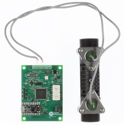
The MAX35103EVKIT2 provides an application example using the MAX35103 time-to-digital converter to measure water flow as part of an off-the-shelf residential irrigation system. The kit includes a PCB and an ultrasonic transducer assembly that can be added to standard 24VAC irrigation systems in order to provide enhanced shut-off irrigation control.
The kit features a MAX32620 Cortex-M4 low-power MCU that executes application firmware. Debug support is provided by a 10-pin JTAG connector and a 3.3V TTL UART connector. Future mBed support is provided by the included MAX32625PICO module.
The kit is designed to be inserted between a 24VAC irrigation controller and an irrigation valve. The valve and controller are optional and are not included but can easily be obtained at most home improvement retailers
Pinout

MAX35103 API and example application
The MAX35103 API and the volumetric example application are availble at github:
https://github.com/maxim-ic-flow/volumetric
A development branch called 'mbed' is available for use with the mbed-cli. the mbed-cli project can be found at:
https://github.com/ARMmbed/mbed-cli .
Compilation using the online compiler is not yet available.
Getting Started with the MAX35103EVKIT2
This section provides instructions to quickly validate basic board and transducer functionality.
1. Connect the main power source
The MAX35103EVKIT requires a 24V AC or DC power source (not included). This is typically the same power source used to power a standard residential irrigation controller (24VAC), but can be a separate 24VAC or DC power adapter. When the board is powered correctly, the red LED will illuminate. Refer to the pinout section to identify the screw-down terminals to use for power.
2. Connect the included ultrasonic transducer assembly to the PCB
The included transducer assembly has two ultrasonic piezo transducers, one which transmits in the "up" direction (typically counter-current) and one that transmits in the opposite direction (down, or typically with the liquid flow). Each transducer should be connected to the PCB via the screw-down terminal. Refer to the pinout section for details.
3. Fill the flow body with water
The transducer assembly is designed to measure liquid flow. The transducers will not work in air. In order to demonstrate basic functionality, simply fill the transducer with water and cap each end with 3/4" NPTF PVC caps (not included but available at any home improvement retailer). Alternatively, immerse the entire assembly in water. Make sure that there are no air bubbles within the transducer assembly.
4. Connect the MAX35103EVKIT2 to a PC
Use the USB lead to connect your mbed to a PC. The status light will come on, indicating it has power. After a few seconds of activity, the PC will recognise the mbed Microcontroller as a standard USB drive.
5. Click the MBED.HTM link to get logged in
Go to the new USB Drive, and click MBED.HTM to open it in a web browser.
If you do not have an mbed account, choose "Signup", and create your mbed Account. Otherwise, log in with your normal username and password.
This will give you access to the website, tools, libraries and documentation.
Technical Reference
Please refer to the MAX35103EVKIT2 datasheet.

Board Partner
Maxim Integrated
Maxim's microcontrollers provide low-power, efficient, and secure solutions for challenging embedded applications.
Silicon Partner
Arm
Arm Holdings is the world's leading semiconductor intellectual property (IP) supplier and as such is at the heart of the development of digital electronic products. Headquartered in Cambridge, UK, Arm has offices around the world, including design centers in Taiwan, France, India, Sweden, and the US.