LPCXpresso55S69
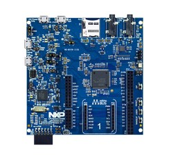
The LPCXpresso55S69-EVK development board provides the ideal platform for evaluation of and development with the LPC55S6x MCU based on the Arm Cortex-M33 architecture. The board includes a high performance onboard debug probe, audio subsystem and accelerometer, with several options for adding off-the-shelf add-on boards for networking, sensors, displays, and other interfaces.
MCU Features
The LPC55S6x MCU family builds on the world’s first general-purpose Cortex-M33 based microcontroller introduced with the LPC5500 series. This high-efficiency family leverages the new Armv8-M architecture to introduce new levels of performance and advanced security capabilities including TrustZone-M and co-processor extensions. The LPC55S6x family enables these co-processors extensions and leverages them to bring significant signal processing efficiency gains from a proprietary DSP accelerator offering a 10x clock cycle reduction. An optional second Cortex-M33 core offers flexibility to balance high performance and power efficiency.
In addition, the LPC55S6x MCU family provides benefits from 40nm NVM based process technology cost advantages, broad scalable packages, and memory options.
- Main Cortex-M33 core with TrustZone, MPU, FPU, SIMD running at up to 100MHz
- Arm Cortex-M33 co-processor running at up to 100MHz
- 640 KB Flash
- 320 KB SRAM
- DSP coprocessor (main core)
- Security features
- On-the-fly code decryption/execution with no performance penalty
- AES256 encryption/decryption engine
- SHA2 module with dedicated DMA controller
- Physically uncloneable function (PUF) for unique device identification and key storage
- Random number generator
128-bit unique device identifier Secure GPIO
- Digital peripherals
- Up to 9 Flexcomm serial peripherals, each providing I2C, I2S, USART or SPI interface
- High and full speed host/device USB controllers with on-chip PHYs
- Dual SDIO and SD/MMC interfaces with DMA support
- Programmable logic unit
- Secure and non-secure region DMA controllers, supporting all DMA-capable peripherals and memory
- Up to 64 GPIOs
- Analog features
- 16-bit ADC with 5 differential pairs sampling at up to 1MS/s
- Temperature sensor
- 5-input comparator
- Timers
- 5 general purpose asynchronous timers
- State controlled timer with up to 8 inputs and 10 output functions
- 24-bit multi-channel/multi-rate timer for repetitive interrupt generation at up to 4 rates
- Windowed watchdog timer
- 42-bit OS timer as continuous system time base
- Clocks
- 96MHz and 32kHz free running oscillators with 1% accuracy
- Support for 1-25MHz and real time (32kHz) crystals
- PLL and LLL for full speed device operation without external high speed clock
- Power management
- Power management unit with 5 low power modes available
- Micro-tick timer running from Watchdog oscillator and RTC can be used for exit from low power modes
- Brownout detection
Board Features
The LPCXpresso55S69 development board provides the ideal platform for evaluation of and development with the LPC55S6x MCU based on the Arm® Cortex®-M33 architecture. The board includes a high performance on-board debug probe, audio subsystem and accelerometer, with several options for adding off-the-shelf add-on boards for networking, sensors, displays and other interfaces.
- LPC55S69 dual core Arm Cortex-M33 microcontroller running at up to 100 MHz
- UART and SPI port bridging from LPC55S69 target to USB via the onboard debug probe
- 3 x user LEDs, plus Reset, ISP (3) and user buttons
- Micro SD card slot (4-bit SDIO)
- Stereo audio codec with line in/out
- High and full speed USB ports with micro A/B connector for host or device functionality
- MikroEletronika Click expansion option
- LPCXpresso-V3 expansion option compatible with Arduino UNO
- PMod compatible expansion / host connector
- Onboard Sensors
- On-board Debug and Programming Interface Circuit with High Speed USB interface
- [USB MSC] Drag-n-drop programming
- [USB CDC] USB Serial Port
- [USB HID] CMSIS-DAP
Important Notes
This platform currently supports Arm Compiler 6 and GCC 7 only. A small number of tests have been found to fail with GCC 6 and IAR 8.
Support for the following features of LPCXpresso55S69 are currently in development in Mbed OS. Schedule for release is TBD.
- USB
Board Features

Board Pinout
The pinout diagrams below show the expansion interface signals. Arduino UNO shields can be used on these connectors by aligning D15 on the shield and LPCXpresso55S69 board.


Getting Started with Mbed
Firmware update required
Please make sure you have updated your LPCXpresso to the latest firmware to enable the Mbed flash disk interface
1. Connect your microcontroller to a PC
Use the USB lead to connect your Mbed to a PC. The status light will come on, indicating it has power. After a few seconds of activity, the PC will recognise the Mbed Microcontroller as a standard USB drive.
 |  |
| Windows XP example | Mac OS X example |
2. Click the PRODINFO.HTM link to get logged in
Go to the new USB Drive, and click PRODINFO.HTM to open it in a web browser.
If you do not have an Mbed account, choose "Signup", and create your Mbed Account. Otherwise, log in with your normal username and password.
This will give you access to the website, tools, libraries and documentation.
PC Configuration
Your Mbed Microcontroller can appear on your computer as a serial port. On Mac and Linux, this will happen by default. For Windows, you need to install a driver:
Windows
See Windows-serial-configuration for full details about setting up Windows for serial communication with your Mbed Microcontroller
From a host PC to communicate with Mbed you will need a terminal application. This allows the Mbed Microcontroller to print to your PC screen, and for you to send characters back to your Mbed.
- Terminals - Using Terminal applications to communicate between the Host PC and the Mbed Micrcontroller
Some terminal programs (e.g. TeraTerm) list the available serial ports by name. However, if you do need to know the identity of the serial port so that you can attach a terminal or an application to it:
| Windows | Mac | Linux | ||||
| Find the identity of the COM port by opening ''Device Manager''. To do this navigate ''Start -> Control Panel -> System -> Hardware -> Device Manager''. | To find the device name under Mac OS X, use the command ''ls /dev/tty.usbmodem*'' | To find the device name under Linux, use the command ''ls /dev/ttyACM*'' | ||||
 |  |  |
Downloading A Program
1. Save a program binary (.hex) to the Platform
Download the "Hello World!" binary:
- LPCXpresso55S69: HelloWorld_lpcxpresso55S69.hex
Note: the source code for this program will be seen in the next section.
Save the program binary file to your mbed Microcontroller Disk, just like you would with a normal USB disk. The Status LED will flash as the PC writes the file to the Microcontroller disk. The file is now consumed.
2. Press the Reset Button
When the Reset Button in pressed, the microcontroller will be reset and the last programmed application will begin to run.
3. Hello World!
The Microcontroller is now running the program; flashing LED1 forever! If you reset the Microcontroller, or disconnect and reconnect the power, the program will simply restart.

Open Existing Project
Import programexample-blinky-lpc55s69
Blinking LED example with system statistics printed to terminal
Last commit 01 May 2019 by ![]() NXP
NXP
1. Install Mbed Command Line Interface (CLI)
Follow the url to install and configure Mbed CLI according to your OS:
2. Open a command terminal on your computer
On Windows, in the search bar, type 'Command Prompt', or 'cmd'
3. Import and configure the project
In the command terminal type
mbed import https://os.mbed.com/teams/NXP/code/example-blinky-lpc55s69/
cd example-blinky-lpc55s69
mbed toolchain GCC_ARM
mbed target LPC55S69_NS
4. Compile the project
Type mbed compile
If compilation ends successfully, you will see a path the .hex file that was built.
5. Download the .hex file to the Platform
Save the program hex file to your Mbed Microcontroller Disk, just like you would with a normal USB disk. The Status LED will flash as the PC writes the file to the Microcontroller disk.
6. Press the Reset Button
When the Reset Button in pressed, the newest program on the Mbed Microcontroller Disk will be loaded in to the Microcontroller FLASH memory. The Status LED will flash as this happens.
7. Run the Program
The Microcontroller is now running the program; flashing a user LED forever! If you reset the Microcontroller, or disconnect and reconnect the power, the program will simply restart.
Where Next
Learn more about Mbed OS APIs and tools, to help you create and deploy IoT devices
Technical Reference
Schematics
Data Sheets
Interface Firmware
You need to log in to post a discussion
To compile a program for this board using Mbed CLI, use lpc55s69_ns as the target name.
 Mbed Enabled
- Baseline
Mbed OS support
- Mbed OS 5.14
- Mbed OS 5.15
Example programs
CMSIS support
Find documentation, software examples and the CMSIS Board Support Pack.
LPCXpresso55S69 on keil.arm.com