FRDM-KW24D512
The FRDM-KW24D512 is a low cost development platform for Kinetis® KW24, KW22, and KW21 MCUs.
Overview
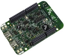
The FRDM-KW24D512 has been designed by NXP in collaboration with mbed for prototyping all sorts of devices, especially those requiring the size and price point offered by Cortex-M4. The board is well sized for low-power applications, thanks to its power efficient Kinetis KW24D512 MCU featuring an ARM® Cortex®-M4 core running up to 50MHz and embedding 512KB Flash, 64KB RAM. The MKW2xD family of devices are used to easily enable connectivity based on the IEEE 802.15.4 Standard. Features on FRDM-KW24D512 include but not limited to RF circuitry including antenna, dual-role USB interface, 16 Mbit external serial flash and 32 MHz reference oscillator crystal. The Kinetis KW24D512 MCU family remains fully software, hardware and development tool compatibility with other Kinetis MCU and Freedom board families. It is packaged as a development board including extension headers compatible with Arduino R3 shields and includes a built-in USB Debug and Flash Programmer.
MCU Features
- Kinetis MKW24D512 in 8x8 LGA package
- Core Processor and Memories
- 50 MHz Cortex-M4 CPU with DSP capabilities
- Up to 512 KB of flash memory
- Up to 64 KB of SRAM
- Typical Applications
- 6LoWPAN
- Thread
- Zigbee (not currently available on mbed OS)
- Home Area Networks consisting of
- Meters
- Gateways
- In-home displays
- Connected appliances
- Networked Building Control and Home Automations with
- Lighting Control
- HVAC
- Security
- Peripherals
- USB
- Cryptographic Acceleration
- 16-bit ADC
- 12-bit DAC
- Flexible timers
- Radio transceiver performance
- Up to –102 dBm receiver sensitivity
- +8 dBm maximum transmit output power
- Up to 58 dBm channel rejection
- Current consumption is minimized with peak transmit current of 17 mA at 0 dBm output power, and peak receive current of 15 mA in Low Power Preamble Search mode.
- Package and Operating Characteristics
- Packaged in an 8 x 8 mm LGA with 56 contacts
- Voltage range: 1.8 V to 3.6 V
Board Features
- Onboard Components
- Integrated PCB inverted F-type antenna and SMA RF port
- FXOS8700CQ - Accelerometer and Magnetometer
- AT45DB161E - 16Mbit External Serial Flash for OTAP support
- 4 user push-buttons
- RGB LED
- Blue LED Indicator
- Connectivity
- Dual role Full-speed USB interface with micro-B USB connector
- up to 3x UARTs, 2x SPIs and 2x I2Cs connected to Headers (multiplexed peripherals)
- Extensions
- Headers compatible with Arduino R3 shields (32-pins / outter row)
- Headers for proprietary shields (32-pins / inner row)
- Analog and Digital IOs (multiplexed peripherals)
- 1x ADC 16-bit resolution with 9 Analog I/O Pins connected to Headers
- up to 1x timers with 7 PWM signals accessible from Headers
- up to x2 Comparator Inputs
- up to 23 MCU I/O Pins connected to Headers (3.3v)
- Board power-supply options (onboard 5 to 3.3V regulator)
- USB Debug 5V
- USB Target 5V
- 5-9V Vin on Arduino headers
- 3.3V/5V PWR input
- Coin-cell 3.3V
- Clocks
- 32 MHz reference oscillator
- 32 kHz clock oscillator
- Integrated OpenSDA USB Debug and Programming adapter
- Several industry standard Debug interfaces (PEmicro, CMSIS-DAP, JLink)
- Drag-n-drop MSD Flash-programming
- Virtual USB to Serial Port
- Form factor: 3.2” x 2.1” / 81mm x 53mm
- Software Development Tools
- mbed HDK & SDK enabled
- Online development tools
- Easy to use C/C++ SDK
- Lots of published libraries and projects
- Alternate Offline options NXP free MCUXpresso IDE (compiler toolchain) and MCUXpresso SDK library/examples
- Supplier website: http://www.nxp.com/frdm-kw24d512
Board Block Diagram
The graphic below gives an overview of the board features and the connection between the target MCU and the on-board components and connectors

Board Pinout
Component Pinout
Following figure indicates the Kinetis KW24D512 signal connections with the board components (RGB LED, Motion Sensor) and extension connectors (External Serial Flash).

Arduino and NXP Header Pinout
Freedom board headers enable up to 64-pins and give access to most of the Kinetis KW24D512 signals
- Outer row pins deliver right signals to meet Arduino R3 standard
- Inner row is connected to up to 32 additional Kinetis KW24D512 pins

Important Notes
Please note that on this MCU in SPI Slave mode pins labeled MOSI behave as Slave Output and pins labeled MISO behave as Slave Input. The terms MOSI (Master Out Slave In) and MISO (Master In Slave Out) only apply to Master mode.
The FRDM-KW24D512 is fully supported in the mbed platform, so it gets access to the free tools and SDK that provides experienced embedded developers with powerful and productive tools for building proof-of-concepts. The pinout above shows the commonly used interfaces and their locations. Note that all the numbered pins (PT_XX) can also be used as DigitalIn and DigitalOut interfaces.
Pin names
PC Configuration
Your mbed Microcontroller can appear on your computer as a serial port. On Mac and Linux, this will happen by default. For Windows, you need to install a driver:
Windows
See Windows-serial-configuration for full details about setting up Windows for serial communication with your mbed Microcontroller
From a host PC to communicate with mbed you will need a terminal application. This allows the mbed Microcontroller to print to your PC screen, and for you to send characters back to your mbed.
- Terminals - Using Terminal applications to communicate between the Host PC and the mbed Micrcontroller
Some terminal programs (e.g. TeraTerm) list the available serial ports by name. However, if you do need to know the identity of the serial port so that you can attach a terminal or an application to it:
| '''Windows''' | '''Mac''' | '''Linux''' | ||||
| Find the identity of the COM port by opening ''Device Manager''. To do this navigate ''Start -> Control Panel -> System -> Hardware -> Device Manager''. | To find the device name under Mac OS X, use the command ''ls /dev/tty.usbmodem*'' | To find the device name under Linux, use the command ''ls /dev/ttyACM*'' | ||||
 |  |  |
Firmware Update
FirmwareUpdate
A new interface firmware image is necessary to mbed-enable NXP FRDM boards
For FRDM-KW24D512, at the following link, choose CMSIS-DAP firmware that is compatible with OpenSDA v2.1 bootloader.
Quick Summary: hold down the reset button, plug in the usb cable to the OpenSDA usb connection, copy the new interface firmware to the enumerated drive, done!
Get Started with mbed
First board connection
Use the USB lead to connect your mbed to a PC. The status light will come on, indicating it has power. After a few seconds of activity, the PC will recognize the mbed Microcontroller as a standard USB drive.
 |  |
| Windows 7 example | Mac OS X example |
Flash a project binary
1. Download a (.bin) to the FRDM Platform
Download the appropriate "Hello World!" binary:
- NXP FRDM-KW24D512: HelloWorld_KW24D.bin
Note: the source code for this program will be seen in the next section.
Save the program binary file to your mbed Microcontroller Disk, just like you would with a normal USB disk. The Status LED will flash as the PC writes the file to the Microcontroller disk.

2. Press the Reset Button
When the Reset Button in pressed, the newest program on the mbed Microcontroller Disk will be loaded in to the Microcontroller FLASH memory. The Status LED will flash as this happens.
When the program is has been loaded onto the microcontroller, it will then start it running.
3. Run Hello World!
The Microcontroller is now running the program; flashing LED1 forever! If you reset the Microcontroller, or disconnect and reconnect the power, the program will simply restart.
4. Flash a new precompiled program
It is the newest program on the mbed Microcontroller that is run after reset. We can therefore download a new program or overwrite an existing one to update the program that will run.
Open existing Project
1. Import the Program to your mbed compiler
Select Import As Program
Choose Import Name of your preference
Click on Import
[Repository '/teams/mbed-os-examples/code/mbed-os-example-blinky/' not found]
2. Compile the Program
In the right panel Program Workspace Select the program you want to compile
Click on Compile in toolbar
If compilation ends successfully, you should see the comment Success! displayed in the Compile Output window available in the bottom and your web browser should download automatically the precompiled binary for the program.
3. Download a (.bin) to the FRDM Platform
Save the program binary file to your mbed Microcontroller Disk, just like you would with a normal USB disk. The Status LED will flash as the PC writes the file to the Microcontroller disk.
4. Press the Reset Button
When the Reset Button in pressed, the newest program on the mbed Microcontroller Disk will be loaded in to the Microcontroller FLASH memory. The Status LED will flash as this happens.
When the program is has been loaded onto the microcontroller, it will then start it running.
5. Run the Program
The Microcontroller is now running the program; flashing LED1 forever! If you reset the Microcontroller, or disconnect and reconnect the power, the program will simply restart.
Program Examples
Congratulation, you have successfully compiled your first project example, you will find more program examples for the FRDM-KW24D512 board available on the right panel of this page or at the NXP code repositories
Example mesh application for mbed OS
1. Import the Program to your mbed compiler
Click Import this application button.
Set ‘radio-type’ to ‘KW24D’ in mbed_app.json.
Change the channel settings: See the file mbed_app.json for an example of defining an IEEE 802.15.4 channel to use.
[Repository '/teams/mbed-os-examples/code/mbed-os-example-mesh-minimal/' not found]
2. Change the Driver
To run a 6LoWPAN-ND network, you need a working RF driver for Nanostack. This example uses the Atmel AT86RF233 by default.
1.Uninstall the Atmel RF driver.
2.Install the new driver for the FRDM-CR20A radio shield based on the MCR20A device.
You can find the driver inside this example program page.
3. Compile the Program
Compile the application.
A binary is generated at the end of the build process.
4. Connect the RF shield to the board
Place the FRDM-CR20A shield on top of your board and power it up.
5. Program the target
Drag and drop the binary to the target to program the application.
Update the firmware of the border router.
You can read the instructions on updating the firmware of your K64F working as 6LoWPAN border router here .
Please do not forget to connect the Ethernet cable between the border router and your home/office router. Then power up the board.
6. Testing
As soon as both the border router and the target are up and running you can verify the correct behaviour. Open a serial console and see the IP address obtained by the device.
Note: This application uses a baud rate of 115200.
Quote:
connected. IP = 2001:db8:a0b:12f0::1
You can use this IP address to ping from your PC and verify that the connection is working correctly.
Create new Project
Follow the guide to creating your own programs using the online compiler
Technical Doc
FRDM-KW24D512 Board
Kinetis KW24D512 MCU
- Fact Sheet
- Data Sheet
- Reference Manual
- USB-KW2x Hardware Reference Manual
- Application Note - Wireless Coexistence in the 2.4 GHz Band
- Application Note - Low-Power Modes on MKW2x Family
- Application Note - Hardware Design Considerations for MKW2x IEEE 802.15.4 Devices
FXOS8700 Motion Sensor
AT45 16-Mbit Data Flash
- Driver
- Usage
DataFlashBlockDevice dataflash(PTC6, PTC7, PTC5, PTC4); //mosi, miso, sclk, csel
Where to buy

You need to log in to post a discussion
To compile a program for this board using Mbed CLI, use kw24d as the target name.
 Mbed Enabled
- Baseline
Mbed OS support
- Mbed OS 2
- Mbed OS 5.10
- Mbed OS 5.11
- Mbed OS 5.12
- Mbed OS 5.13
- Mbed OS 5.14
- Mbed OS 5.15
- Mbed OS 5.5
- Mbed OS 5.6
- Mbed OS 5.7
- Mbed OS 5.8
- Mbed OS 5.9
Example programs