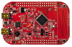
FRDM-KL27Z
The FRDM-KL27Z is an ultra-low-cost development platform for the Kinetis® L Series KL17 and KL27 MCUs built on the ARM® Cortex®-M0+ processor
Overview
The FRDM-KL27Z has been designed by NXP in collaboration with mbed for prototyping all sorts of devices, especially those requiring the size and price point offered by Cortex-M0+. The board is well sized for ultra-low-power applications, thanks to its power efficient Kinetis KL43 MCU featuring an ARM® Cortex®-M0+ core running up to 48MHz. The Kinetis KL27 MCU family remains fully software, hardware and development tool compatibility with Kinetis MCU and Freedom board families. It is packaged as a development board including extension headers compatible with Arduino R3 shields and includes a built-in USB Debug and Flash Programmer.
MCU Features
- Kinetis MKL27Z64VLH4 in 64LQFP package
- ARM® Cortex™-M0+ 32-bit core
- 48 MHz max CPU frequency
- 64 KB program flash memory
- 16 KB RAM
- 16kb ROM with built-in bootloader
- Multiple low-power modes, low-leakage wake-up unit
- 4-channel DMA controller
- 3x Internal Reference Clocks, 2x Crystal inputs
- 3x UART modules, supporting ISO7816
- 2x SPI modules
- 2x I2C modules
- 1x FlexIO module
- 1x USB 2.0 full speed, crystal-less
- 1x segment LCD
- 1x 16-bit ADC, 1x 6-bit DAC
- 6x Timers
- Up to 51x GPIOs
- Advanced flash security
Board Features
- Onboard Components
- MMA8451Q accelerometer
- MAG3110 magnetometer
- Capactive touch slider
- 2 user push-buttons
- 1 RGB LED
- Thermistor sensor
- Connectivity
- Dual-role USB full-/low-speed Device controller with crystal-less feature
- up to 3x UARTs, 2x SPIs and 1x I2C connected to Headers (multiplexed peripherals)
- Extensions
- Headers compatible with Arduino R3 shields (32-pins / outter row)
- Headers for proprietary shields (32-pins / inner row)
- Analog and Digital IOs (multiplexed peripherals)
- 1x ADC 16-bit resolution with 16 Analog I/O Pins connected to Headers
- up to three timers with 28 PWM signals accessible from Headers
- up to two Comparator Inputs
- up to 40 MCU I/O Pins connected to Headers (3.3v, 4mA each, 400mA max total)
- Board power-supply options (onboard 5 to 3.3V regulator)
- USB Debug 5V
- USB Target 5V
- 5-9V Vin on Arduino headers
- 5V PWR input
- Coin-cell 3.3V
- Integrated OpenSDA USB Debug and Programming adapter
- Several industry standard Debug interfaces (PEmicro, CMSIS-DAP, JLink)
- Drag-n-drop MSD Flash-programming
- Virtual USB to Serial Port
- Form factor: 3.2” x 2.1” / 81mm x 53mm
- Software Development Tools
- mbed HDK & SDK enabled
- Online development tools
- Easy to use C/C++ SDK
- Lots of published libraries and projects
- Alternate Offline options NXP free MCUXpresso IDE and SDK library/examples
Board Block Diagram
The graphic below gives an overview of the board features and the connection between the target MCU and the on-board components and connectors

Board Pinout
Arduino and NXP Header Pinout
Freedom board headers enable up to 64-pins and give access to most of the Kinetis KL27 signals
- Outer row pins deliver right signals to meet Arduino R3 standard
- Inner row is connected to up to 32 additional Kinetis KL27 pins

Important Notes
Please note that on this MCU in SPI Slave mode pins labeled MOSI behave as Slave Output and pins labeled MISO behave as Slave Input. The terms MOSI (Master Out Slave In) and MISO (Master In Slave Out) only apply to Master mode.
The FRDM-KL27Z is fully supported in the mbed platform, so it gets access to the free tools and SDK that provides experienced embedded developers with powerful and productive tools for building proof-of-concepts. The pinout above shows the commonly used interfaces and their locations. Note that all the numbered pins (PT_XX) can also be used as DigitalIn and DigitalOut interfaces.
Pin names
PC Configuration
Your mbed Microcontroller can appear on your computer as a serial port. On Mac and Linux, this will happen by default. For Windows, you need to install a driver:
Windows
See Windows-serial-configuration for full details about setting up Windows for serial communication with your mbed Microcontroller
From a host PC to communicate with mbed you will need a terminal application. This allows the mbed Microcontroller to print to your PC screen, and for you to send characters back to your mbed.
- Terminals - Using Terminal applications to communicate between the Host PC and the mbed Micrcontroller
Some terminal programs (e.g. TeraTerm) list the available serial ports by name. However, if you do need to know the identity of the serial port so that you can attach a terminal or an application to it:
| Windows | Mac | Linux | ||||
| Find the identity of the COM port by opening ''Device Manager''. To do this navigate ''Start -> Control Panel -> System -> Hardware -> Device Manager''. | To find the device name under Mac OS X, use the command ''ls /dev/tty.usbmodem*'' | To find the device name under Linux, use the command ''ls /dev/ttyACM*'' | ||||
 |  |  |
Firmware Update
FirmwareUpdate
A new interface firmware image is necessary to mbed-enable NXP FRDM boards. Please follow the link below to get the latest firmware application (DAPLink rev0242 found in step 2). Then follow steps 3 and 4 on NXP OpenSDA page.
Get Started with mbed
First board connection
Use the USB lead to connect your mbed to a PC. The status light will come on, indicating it has power. After a few seconds of activity, the PC will recognise the mbed Microcontroller as a standard USB drive. (Note that the drive name should be customized for FRDM-KL27Z)
 |  |
| Windows 7 example | Mac OS X example |
Connect to mbed
Go to the new USB Drive, and click MBED.HTM to open it in a web browser.
If you do not have an mbed account, choose "Signup", and create your mbed Account. Otherwise, log in with your normal username and password.
This will give you access to the website, tools, libraries and documentation.
Mbed 2 Supported
This platform supports Mbed 2 with ARM and IAR toolchains. Please be advised that applications built with GCC_ARM toolchain for this target may result in memory overflow.
Flash a project binary
1. Download a (.bin) to the FRDM Platform
Download the appropriate "Hello World!" binary:
- NXP FRDM-KL27Z: HelloWorld_KL27Z.bin
Note: the source code for this program will be seen in the next section.
Save the program binary file to your mbed Microcontroller Disk, just like you would with a normal USB disk. The Status LED will flash as the PC writes the file to the Microcontroller disk.

2. Press the Reset Button
When the Reset Button in pressed, the newest program on the mbed Microcontroller Disk will be loaded in to the Microcontroller FLASH memory. The Status LED will flash as this happens.
When the program is has been loaded onto the microcontroller, it will then start it running.
3. Run Hello World!
The Microcontroller is now running the program; flashing LED1 forever! If you reset the Microcontroller, or disconnect and reconnect the power, the program will simply restart.
4. Flash a new precompiled program
It is the newest program on the mbed Microcontroller that is run after reset. We can therefore download a new program or overwrite an existing one to update the program that will run.
Open existing Project
1. Import the Program to your mbed compiler
Select Import As Program
Choose Import Name of your preference
Click on Import
Import programmbed_blinky
The example program for mbed pin-compatible platforms
Last commit 08 Apr 2019 by  Mbed
Mbed
2. Compile the Program
In the right panel Program Workspace Select the program you want to compile
Click on Compile in toolbar
If compilation ends successfully, you should see the comment Success! displayed in the Compile Output window available in the bottom and your web browser should download automatically the precompiled binary for the program.
3. Download a (.bin) to the FRDM Platform
Save the program binary file to your mbed Microcontroller Disk, just like you would with a normal USB disk. The Status LED will flash as the PC writes the file to the Microcontroller disk.
4. Press the Reset Button
When the Reset Button in pressed, the newest program on the mbed Microcontroller Disk will be loaded in to the Microcontroller FLASH memory. The Status LED will flash as this happens.
When the program is has been loaded onto the microcontroller, it will then start it running.
5. Run the Program
The Microcontroller is now running the program; flashing LED1 forever! If you reset the Microcontroller, or disconnect and reconnect the power, the program will simply restart.
Program Examples
Congratulation, you have successfully compiled your first project example, you will find more program examples for the FRDM-KL27Z board available on the right panel of this page or at the NXP code repositories
Create new Project
Follow the guide to creating your own programs using the online compiler
Technical Doc
FRDM-KL27Z Board
Kinetis KL27 MCU
- Data Sheet
- Reference Manual
- Errata
- Application Note -Generating a Fixed Number of PWM Pulses Using TPM and DMA
MMA8451Q Accelerometer
MAG3110 Magnetometer
Where to buy

You need to log in to post a discussion
To compile a program for this board using Mbed CLI, use kl27z as the target name.
 Mbed Enabled
- Baseline
Mbed OS support
- Mbed OS 2
Example programs
CMSIS support
Find documentation, software examples and the CMSIS Board Support Pack.
FRDM-KL27Z on keil.arm.com