EV-COG-AD3029LZ
EV-COG-AD3029LZ is an IoT Development Platform based on ADuCM3029 MCU for Ultra Low Power Applications.
Overview
The EV-COG-AD3029LZ is a development platform based on the industry leading ultra low power ADuCM3029 32-bit ARM Cortex™-M3 microcontroller. The platform is designed to be an advanced development and prototyping vehicle to get customer ideas from concept to production with lower risk and faster time to market. A free version of CrossCore Embedded Studios (an Eclipse based Analog Devices Interactive Development Environment) is available for application development and debug. Add-on hardware modules, MCU drivers and software application examples help form a complete ecosystem that customers can leverage into their final product.
Features
MCU Features
- Analog Devices ADuCM3029 processor in 64-pin LFCSP package
- Performance
- ARM Cortex-M3 32-bit RISC core running at 26MHz
- Memory
- 64kB of SRAM with parity
- 256kB of embedded flash memory with ECC
- 32kB of retainable SRAM in hibernation
- Optional 4kB of cache for lower active power
- Power Dissipation
- 30uA/MHz in full Active mode
- < 300uA in Flexi mode
- < 730nA in Hibernation mode
- < 60nA in Shutdown mode
- Clocks
- 32kHz and 26MHz on-chip oscillator with programmable divider
- Timers
- 3 general purpose timers with PWM support
- 2 Real Time Clocks (RTC) with programmable beeper & SensorStrobe support
- 1 watchdog timer
- Digital Peripherals
- 3 SPI
- 1 I2C
- 1 UART
- 1 SPORT
- 44 programmable GPIOs
- 25 channel DMA controller
- Analog I/O
- 8 channel 12-bit SAR ADC supporting sampling rates up to 1.8MSPS
- Security
- User code protection
- True Random Number Generator (TRNG)
- Hardware CRC accelerator
- Hardware crypto accelerator for AES-128/AES-256/SHA-256
- Electrical Characteristics
- Single supply operation: 1.74 - 3.6V
- Optional buck converter for improved efficiency
Board Features
- CMSIS-DAP compatible debugging interface
- Drag-n-drop flash programming
- JLink-9 Interface
- Multiple board power options - USB, coin cell, Li-Ion battery or external (via add-on board)
- ADXL362 accelerometer
- ADT7420 temperature sensor
- 2 user programmable push buttons
- 2 user programmable LEDs
- RF module connection headers
- Expansion connectors for add-on boards
- Arduino connector
- Standard 0.1" connectors for GPIO access
- ADI ADF-70xx RF daughter-card connector
- Compatible with offline development tools:
- CrossCore Embedded Studio 2.6.0
- ARM Keil uVision 5
- IAR Embedded Workbench 7.8
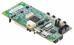
Board Layout
EV-COG-AD3029LZ Top View

EV-COG-AD3029LZ Bottom View

Peripheral Devices Pinout

Add-on Boards
The EV-COG-AD3029LZ board has expansion connectors which allow add-on hardware modules to be connected to offer additional capabilities such as radio transceivers and Arduino interfaces. Some of the currently available add-on hardware modules are listed below:
EV-COG-BLEINTP1Z Connectivity COG Board

This connectivity add-on module enables wireless RF transceiver connectivity, The board comes with Bluetooth Low Energy connectivity and it provides a set of connectors upon which other radio boards can be added.
EV-GEAR-EXPANDER1Z Expander Gear

This add-on module enables easy access to all the GPIO pins on the ADuCM3029 MCU. It provides PMOD connectors to interface to various ADI PMOD based sensor boards, Arduino uno connectors for connecting to compatible Arduino Shields as well as a SD card slot for data storage.
Board Pinout

Firmware
Please follow the firmware update instructions to update the interface firmware on the board.
Getting Started with mbed
1. Connect your microcontroller to a PC
Use the USB lead to connect your mbed to a PC. The status light will come on, indicating it has power. After a few seconds of activity, the PC will recognise the mbed Microcontroller as a standard USB drive.
 |
| Windows 7 example |
2. Click the MBED.HTM link to get logged in
Go to the new USB Drive, and click MBED.HTM to open it in a web browser.
If you do not have an mbed account, choose "Signup", and create your mbed Account. Otherwise, log in with your normal username and password.
This will give you access to the website, tools, libraries and documentation.
PC Configuration
Your mbed Microcontroller can appear on your computer as a serial port. On Mac and Linux, this will happen by default. For Windows, you need to install a driver:
Windows
See Windows-serial-configuration for full details about setting up Windows for serial communication with your mbed Microcontroller
From a host PC to communicate with mbed you will need a terminal application. This allows the mbed Microcontroller to print to your PC screen, and for you to send characters back to your mbed.
- Terminals - Using Terminal applications to communicate between the Host PC and the mbed Micrcontroller
Some terminal programs (e.g. TeraTerm) list the available serial ports by name. However, if you do need to know the identity of the serial port so that you can attach a terminal or an application to it:
| Windows | Mac | Linux | ||||
| Find the identity of the COM port by opening ''Device Manager''. To do this navigate ''Start -> Control Panel -> System -> Hardware -> Device Manager''. | To find the device name under Mac OS X, use the command ''ls /dev/tty.usbmodem*'' | To find the device name under Linux, use the command ''ls /dev/ttyACM*'' | ||||
 |  |  |
Downloading A program
1. Save a program binary (.bin) to the Platform
Download the appropriate "Hello World" binary:
- EV-COG-AD3029LZ: Hello_World_cog3029.bin
Note: the source code for this program will be seen in the next section.
Save the program binary file to your mbed Microcontroller Disk, just like you would with a normal USB disk. The Status LED will flash as the PC writes the file to the Microcontroller disk. The file is now consumed.
2. Press the Reset Button
When the Reset Button in pressed, the microcontroller will be reset and the last programmed application will begin to run.
3. Hello World!
The Microcontroller is now running the program; flashing LED1 forever! If you reset the Microcontroller, or disconnect and reconnect the power, the program will simply restart.
Building Hello World!
The hello world application can be built using the online compiler:
1. Click on this link to import the mbed blinky project into the online compiler.
2. Click import button when prompted.
3. Click compile button to build the project. At the end of the build process, the compiler will prompt you to download the flash image file.
4. Download the flash image and drag-n-drop it into the device mbed disk and power cycle the board.
Where Next
Follow the guide to creating your own programs using the online compiler
Technical Reference
Power
- USB powered or 4.5v - 9v on Vin pin
- Current (active): < 780uA
- Current (sleep): < 730nA
- 3.3v regulated output on VOUT to power peripherals
- 5.0v from USB available on 5v (only available when USB is connected unless extra regulator is added!)
- Digital IO pins are 3.3v, 4mA each, 400mA max total
Schematics
Data Sheets
- ADuCM3029 Data Sheet
- ADuCM3029 Hardware Reference Manual
- ADuCM3029 Errata Sheet
- ADXL362 3-Axis Accelerometer Data Sheet
- ADT7420 Temperature Sensor Data Sheet
Interface Firmware

To compile a program for this board using Mbed CLI, use ev_cog_ad3029lz as the target name.
Board Partner
Analog Devices
ADI enables our customers to interpret the world around us by intelligently bridging the physical and digital with unmatched technologies that sense, measure and connect. We collaborate with our customers to accelerate the pace of innovation and create breakthrough solutions that are ahead of what’s possible.
 Mbed Enabled
- Baseline
Mbed OS support
- Mbed OS 5.10
- Mbed OS 5.11
- Mbed OS 5.12
- Mbed OS 5.13
- Mbed OS 5.14
- Mbed OS 5.15
- Mbed OS 5.6
- Mbed OS 5.7
- Mbed OS 5.8
- Mbed OS 5.9
- Mbed OS 6.0
- Mbed OS 6.1
- Mbed OS 6.10
- Mbed OS 6.11
- Mbed OS 6.12
- Mbed OS 6.13
- Mbed OS 6.14
- Mbed OS 6.15
- Mbed OS 6.2
- Mbed OS 6.3
- Mbed OS 6.4
- Mbed OS 6.5
- Mbed OS 6.6
- Mbed OS 6.7
- Mbed OS 6.8
- Mbed OS 6.9
Example programs
CMSIS support
Find documentation, software examples and the CMSIS Board Support Pack.
EV-COG-AD3029LZ on keil.arm.com