DC motor with encoder programming

10 Sep 2018

Hi I am new to programming in general and have recently started using a stm32 F401RE nucleo board to control a DC motor with encoder with a L298N module as the motor driver. I wrote a simple program that should allow me to control the DC motor's rotation and speed if the values are changed. /media/uploads/colonelex/screenshot_-1-.png
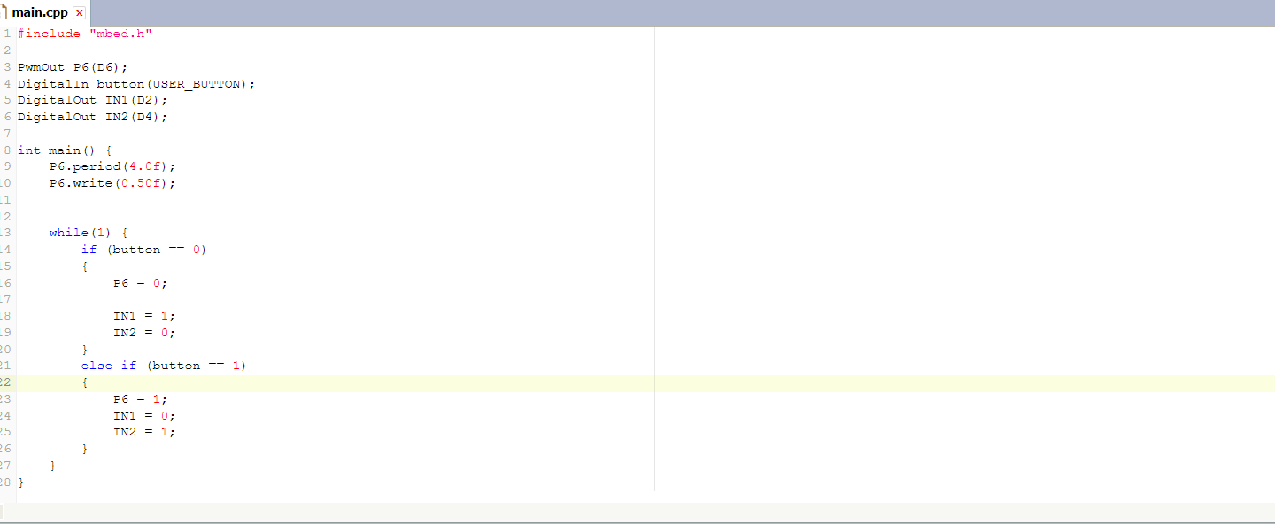
With this, I can change the rotation of the motor using the user button but the motor speed does not seem to be controlled by the pwm output pin. Furthermore, the DC motor is fitted with an encoder and I need to be able to measure distance moved by the motor but have no idea how to control the A and B channels of the encoder to do so. Any help provided will be well appreciated.

DC motor- part number 110055 https://servo.com.sg/sites/default/files/2018-01/A-max_Program_2017-18_0.pdf

encoder- part number110078 https://www.maxonmotor.com/medias/sys_master/root/8825854328862/17-EN-393-394.pdf

11 Sep 2018

Hi Zhao,

It is certainly possible to use various of the STM32F401 hardware timers in quadrature encoder mode, and I have used them for this function on a F405. look at the STM32F401reference manual https://www.st.com/resource/en/reference_manual/dm00096844.pdf, you have a choice of TIM1,TIM2,TIM3,TIM4,TIM5

See section 13.3.12 of the manual Encoder interface mode for the exact details for TIM2-5. I believe that TIM2- 5 are slightly easier to use than TIM1. You use the TIMx->ARR register to set up the maximum count, then the count is always modulo that value. Once set up the latest count can be read from the TIMx->CNT register.

regards Andy

12 Sep 2018

Hi Andy

Thanks for the quick reply. Can these settings of the timers be done in the online compiler or do I have to use other programs such as the Stm32 Cube mx?

https://os.mbed.com/users/zoot661/code/encoderTest/

Before this I tried to use the code above to do a test by connecting to D7 and D8 pins but doesn't seem to have any feedback from the encoder on my laptop. In fact, I do not know if there is any two-way communication between my laptop and the stm32 board since I just flash the bin file into the drive.

Regards Zhao Meng

12 Sep 2018

Hi Zhao,

If you are a beginner then the code in the link you give looks like a good place to start. I would start at the beginning. First get the Blinky project working. https://github.com/ARMmbed/mbed-os-example-blinky

Once you have that working then you can build up very quickly to more complicated things.

However to answer your other questions,

You can certainly do this in STM32Cube. There is an option to enable a timer in quadrature encoder mode, right at the bottom of the timer section in the pinout tab.

You can also do it in the mbed online compiler, but it will be a hard slog to write the low level registers, especially if you are a beginning programmer. I did a test to verify if it is possible to access the STM32F4 hardware registers using the online compiler and published the results.

https://os.mbed.com/users/skyscraper/code/Nucleo_BareMetal_QuadratureEncoder/file/c1a4bf56f1de/main.cpp/

Note that won't work yet as a quadrature encoder. It was just a test to see if it will compile, which it does seem to do.

As I mentioned before, I have a working STM32F4 quadrature encoder but using a different syntax. The hardware works very well:

https://github.com/kwikius/quantracker/blob/master/ground/tracker/v1/azimuth_encoder.cpp

Note: I dont know if mbed sets up the STM32 MPU privileged mode which would prevent direct access to the registers. That would need testing out.

regards Andy

14 Sep 2018

Hi Andy

Thanks for the suggestions. Will be trying the Blinky project to start.

/media/uploads/colonelex/main.cpp

I found this code in one of the forum and it looks very comprehensive and compiled successfully on the online compiler but nothing happens when flashed onto the nucleo board. Not sure why that happens.

Regards Zhao Meng

15 Sep 2018

Hi Zhao,

I would suggest to do a "blinky" app to blink an LED first. Once that works then you know that your upload tools are working.

Once you have "blinky" working , then try a "Hello World" app that sends some text to the PC serial port. Then you know that your serial port settings such as port and baud-rate and your serial port terminal application are working correctly.

Once those parts are all working then try the encoder program in the link. If it doesnt work then you can put debug statements in at various points to see where it stopped working.

regards Andy

17 Sep 2018

Hi Andy

It turns out that I didn't install a hyper terminal in my PC that's why there wasn't a message sent. Now I just need to figure out how to run both the DC motor and the encoder at the same time and how to make the DC motor stop when the encoder reads a certain distance.

Regards Zhao Meng

20 Sep 2018

Hi Zhao,

That is great.

The best and simplest way to run several things at the same time on the microcontroller is to use an RTOS , e.g https://os.mbed.com/docs/v5.9/reference/rtos.html.

To make a motor stop at a position, the standard way is to use a control feedback algorithm, which gradually slows the motor as it nears its target position. The simplest and most well known is called P.I.D https://en.wikipedia.org/wiki/PID_controller.

regards Andy

28 Sep 2018

Hi Andy

Is there a fixed format for the PID controller? So far I moved the program I initially posted into the encoder program that was found later. There is data read from the encoder but I can't seem to make sense of the bits from it. Also I tried to use .period and .pulsewidth to control the motor speed but doesn't seem to work.

Regards Zhao Meng