Important changes to forums and questions
All forums and questions are now archived. To start a new conversation or read the latest updates go to forums.mbed.com.
Bug: I2c block read/write fails to send repeated start when in fast mode
Topic last updated 01 Feb 2013, by  Wim Huiskamp.
9
replies
Wim Huiskamp.
9
replies
Wim Huiskamp.
9
replies


Hi,
I believe I've found a bug in the I2C block read implementation involving repeated starts and fast mode (400kbps).
Here's the scenario. I have a sensor which requires a write operation immediately followed by a read, with no stop bit in between. This can be implemented using a repeated start like so:
Edit: I've added the full function body including input validation and NoAck based on Wim's comments.
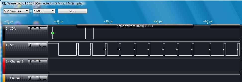
STATUS WriteAndRead(I2cFrequency frequency, int address, unsigned char* txBuffer, int txLength, unsigned char* rxBuffer, int rxLength){
    // Validate inputs
    assert(txBuffer);
    assert(rxBuffer);
    assert(txLength > 0);
    assert(rxLength > 0);

    // Set frequency
    i2c->frequency(frequency);

    // Perform write followed by read
    if(0 != i2c->write(address, (char*)txBuffer, txLength, 1))
        goto NoAck;
    if(0 != i2c->read(address, (char*)rxBuffer, rxLength, 0))
        goto NoAck;
    return SUCCESS;
NoAck:
    return FAILURE;
}
The above code works fine when the frequency is set to 100kbps, however it fails when set to 400kbps. Examining what was happening with an oscilloscope, I saw that at 400kbps the line was never being driven low for the repeated start bit. In other words, while repeated start should omit the stop bit at the end of the write, I was seeing both the stop and the start bits omitted. There was no separation between the last byte of the write and the first byte of the read. This meant that the sensor never responded to the read because it interpreted the address byte as another data byte in the write. At 100kbps the start bit was written correctly and so the sensor responded.
I re-wrote the above code using explicit starts and stops with the single-byte reads and writes, as shown below.
STATUS WriteAndRead(I2cFrequency frequency, int address, unsigned char* txBuffer, int txLength, unsigned char* rxBuffer, int rxLength){
    // Validate inputs
    assert(txBuffer);
    assert(rxBuffer);
    assert(txLength > 0);
    assert(rxLength > 0);

    // Prepare for write
    i2c->frequency(frequency);
    i2c->start();
    if(!i2c->write(address & 0xfe))
        goto NoAck;

    // Perform write
    for(int i=0; i<txLength; i++){
        if(!i2c->write(*txBuffer++))
            goto NoAck;
    }

    // Prepare for read; send a repeated start bit
    i2c->start();
    if(!i2c->write(address | 0x01))
        goto NoAck;

    // Perform read
    for(int i=0; i<rxLength; i++)
        *rxBuffer++ = i2c->read(1);

    // Finish by sending stop bit
    i2c->stop();
    return SUCCESS;

NoAck:
    i2c->stop();
    return FAILURE;
}
This version works fine at all frequencies. Any idea why I am seeing this behaviour?