Wrong USB line termination in official LPC11U24 mbed schematic (TGT D+ D- lines)

06 Oct 2012

Guys,

I've been prototyping new hardware based on the LPC11U24 and I believe I've found a bug on the official mbed LPC11U24, which worries me especially considering many people (such as myself) base our custom designs based on the implied best-practices of the mbed design.

The bug is related to the termination of the USB D+/D- lines connected to the LPC11U24 and (subsequently the broken-out pins D+/D- on the actual mbed).

In almost every other USB implementation I've been able to dig up from multiple vendors (including the LPC1768 mbed!), the resistors and low-pF value caps form a low-pass filter to help reduce interference. In the case of the mbed LPC11U24, it appears the resistors vs capacitors are accidentally reversed!

Have a look at my screenshot with an arrow pointing to where I believe the resistors should actually be. As I mentioned, the mbed LPC1768 does this correctly, as do the D+/D- lines on the mbed magic chips on BOTH mbeds!

BUT, I'm not 100% confident about the validity of my statements because 1) I'm a USB hardware novice and 2) I imagine the @mbed went through multiple levels of review compared to my very novice self. My take on it is that of course the USB features certainly still work most of the time, but the filter is basically reversed, and half as effective at stopping incoming interference (assuming the device at the other end of the connection has the proper termination). In harsh conditions, this *could* negatively affect reliability.

A picture always helps. Here is the mbed LPC11U24 schematic with what I believe are errors:
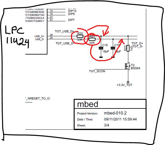
/media/uploads/robodude/mbed-lpc11u24-schematic-error2.jpg

Here is the mbed LPC1768 in comparison which I believe is OK:
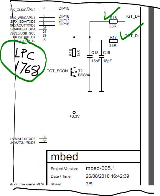
/media/uploads/robodude/mbed-lpc1768-ok.jpg

I would be most grateful if the people @mbed could comment on this, because I have a few designs that I was about to send off for prototyping... but I want to get this right!

PS also notice the 1.5k resistor and BSS84 (T2) is also inconsistently positioned between the two mbed designs!

07 Oct 2012

Seems to me that in practice they are the same. It's an RC low pass-filter, so at very high frequencies the caps works like a short to ground and send those high frequencies signals to ground.

Similar, the 1K5 pullup after or before the 33ohm line terminator does not alter its purpose. That is to pull the D+ line at 3.3V (to signal a full-speed device).

07 Oct 2012

Hey Juan, I agree that both generally work. BUT, putting the caps on the proper side of the 33ohm resistors would double the effectiveness of the filter, assuming a similar termination on the other connected device.

A summary:

  1. mbed LPC1769 magic chip USB : 18pF caps on the inside of the 33ohm resistors
  2. mbed LPC1769 user D+/D- USB : 18pF caps on the inside of the 33ohm resistors
  3. mbed LPC11U24 magic chip USB: 18pF caps on the inside of the 33ohm resistors
  4. mbed LPC11U24 user D+/D- USB: 18pF caps on the outside of the 33ohm resistors (!?)

As you can see above, 3 out of 4 times in the 2 official mbeds, it is done with the caps after the 33ohm resistors. Strangely, the only place this is not the case is on the user D+/D- on the LPC11U24 board... Obviously, this inconsistency doesn't result in a broken mbed (otherwise there'd be several frustrated users)... my question to the mbed team is was this intentional, and which is the better way for our custom PCBs?

Basically, I'd like to know if there was some other reason behind the change, which perhaps I am too novice to know about, or if it was just a relatively inconsequential inconsistency without purpose.

07 Oct 2012

I see your point.

Problem is we don't know what kind of termination is on the other side besides the usual 27-33omh resistors and the lines are bidirectional. I've seen some application notes that doesn't even mention the capacitors but they do enforce the use of a ESD array (which has some low capacitance but usually on the 1pf range).

I have a design now with a TI AM3359 and I'm not using the capacitors on the data line but I'm getting a babble error after some hours of run, maybe those caps will help with my problem.

There is a very nice general USB guide here:

http://www.beyondlogic.org/usbnutshell/usb1.shtml

But. An official word from the team would be great I'm a USB noob too :)

08 Oct 2012

Hello, this reminds me forum post on lpcware.com in lpc1xx section.

Quote:

Oh and I forgot to mention it is not shown on the ap-note, but you *REALLY* want to have a 47pF/NPO capacitor from each USB data-line to ground. This would be in-between the 33-ohm series resistors shown the ap-note and the USB connector. This is because some of the "cheap" hubs that are out on the market will get confused and "lock up" if there is any RF noise on the USB data lines. The 47pF/NPO caps do the trick and this is the case for *ALL* USB devices that you design, no matter what chip you are using. (Some have built-in series resistors, but the caps are always needed). It also helps your device pass EMC testing (less RFI during USB use)

Rest is at http://www.lpcware.com/content/forum/lpc11u24-usb-msd-bootloader-does-it-use-usbconnect

Because I am developing my first own board with lpc11u24 I am very interested in this.

Please add Your suggestions here.

08 Oct 2012

Hi All,

Firstly, Robbie, thanks for pointing this is out. It is indeed a mistake. As you can tell by the swapped position of the FET as well, it is clearly a schematic block cut/paste/flip that has caused this. It will be rectified for future builds of the LPC11U24 mbed, and the published schematic and reference designs will be updated shortly.

The design has gone through various stages of review, but as the 33R/18pF is a fairly standard reference design circuit, and of course the signals are bidirectional so it is easy to see how the design could be rationalised either way around.

As for the effect, the order of the R's, C's and FET at low frequency is negligible. There will be advantages in having the RC filter the right way around in noisy environments. I would expect that it will make little difference to users, except for those deploying the design in the harshest environments.

What's interested me while looking at the wider picture of termination, is that there is a wide variation in what is considered "best practice". Of course there will be no single right answer, and its something that a room with more than 2 people will never be agreed upon. For now, we'll be sticking with the 33R/18pF as per the NXP reference implementation, and I'll be updating the LPC11U24 to reflect that.

Thanks again for point this out!

Chris

08 Oct 2012

Hey Chris, thanks for responding so quickly. Glad to see I wasn't going insane. I too noticed that it was most likely a group-copy/paste-flip mishap in eagle (this is actually how I discovered it in the first place)!

I will go with the official NXP/mbed way, 33R/18pF with the RC filter as shown above in the green LPC1768 implementation in my original post. Perhaps we can call this good practice instead of best practice :)

Thanks again and Cheers!

08 Oct 2012

Hi Robbie,

No worries, and sorry for the confusion its caused, especially if you ever questioned your sanity!

I like your term "good practice" - we can all agree that various different schemes can all count as "good practice" without having to imply someone wins!

Is your design commercially sensitive or would you be happy to shared (some of) what you've done as a guest blog post? We don't seen enough examples of that sort of thing, which is a shame, it would be good to showcase some next-step designs.

Thanks, Chris

08 Oct 2012

Hey Chris - I would love to do a guest post. I actually have one final bug report underway with regards to bare metal deployment of the LPC11U24... this time, in the software realm. I believe I've found the solution, I'm just trying to simplify/verify the exact conditions and solution (I hate false positives as much as the next guy). I'll be in touch!