Porting LoRaWAN stack and LoRa RF drivers
Mbed OS contains a native LoRaWAN stack (inside the Mbed OS tree) augmented with most commonly used LoRa RF drivers (outside the Mbed OS tree). Arm encourages developers around the globe to contribute to any of the Mbed OS features and functionality, including the LoRaWAN stack and related RF drivers using the general guidelines provided.
The information in this section can be classified in two subsections:
- Porting a LoRa RF driver for the Arm Mbed LoRaWAN stack.
- Device design guide to use the Arm Mbed LoRaWAN stack.
The whole porting process consists of two key ingredients:
- An implementation of the LoRaRadio class.
- Design considerations for using LoRaWANInterface class.
Porting a LoRa RF driver
Arm Mbed OS provides a generic API that serves as a template for any LoRa RF driver. LoRaRadio is a pure virtual class and is an attempt to standardize the APIs across all LoRa radios. Mbed Enabled LoRa radio driver implementations present as a LoRaRadio.
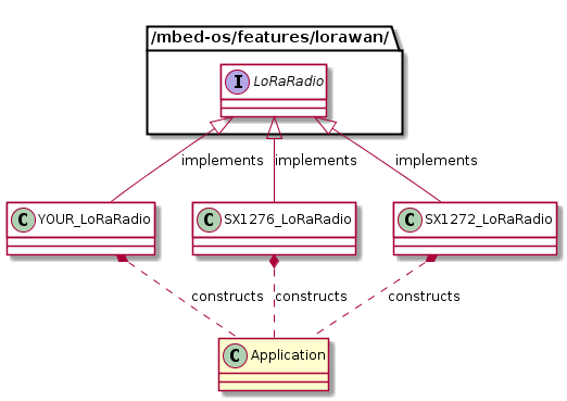 Figure 1. Existing Mbed LoRa RF drivers inherit from the LoRaRadio class.
For a reference implementation, please see the existing LoRa RF drivers. Construction of a LoRaRadio object is a matter of taste. The existing reference drivers allow construction of the LoRaRadio object with full pin definitions to make sure that the driver is usable across boards with any pin combination. You are free to use any form of construction as long as you provide a LoRaRadio object down to the Arm Mbed LoRaWAN stack. Use of an instance of the LoRaRadio class for a third party LoRaWAN stack is beyond the scope of this documentation.
For API use cases, details, explanation and meaning, please see the LoRaRadio class reference below. We carefully planned and designed the data structures provided in LoRaRadio.h. They carry most of what you need to write your LoRa RF driver.
| Public Member Functions | |
| virtual void | init_radio (radio_events_t *events)=0 |
| Registers radio events with the Mbed LoRaWAN stack and undergoes initialization steps, if any. More... | |
| virtual void | radio_reset ()=0 |
| Resets the radio module. More... | |
| virtual void | sleep (void)=0 |
| Put the RF module in sleep mode. More... | |
| virtual void | standby (void)=0 |
| Sets the radio to standby mode. More... | |
| virtual void | set_rx_config (radio_modems_t modem, uint32_t bandwidth, uint32_t datarate, uint8_t coderate, uint32_t bandwidth_afc, uint16_t preamble_len, uint16_t symb_timeout, bool fix_len, uint8_t payload_len, bool crc_on, bool freq_hop_on, uint8_t hop_period, bool iq_inverted, bool rx_continuous)=0 |
| Sets reception parameters. More... | |
| virtual void | set_tx_config (radio_modems_t modem, int8_t power, uint32_t fdev, uint32_t bandwidth, uint32_t datarate, uint8_t coderate, uint16_t preamble_len, bool fix_len, bool crc_on, bool freq_hop_on, uint8_t hop_period, bool iq_inverted, uint32_t timeout)=0 |
| Sets the transmission parameters. More... | |
| virtual void | send (uint8_t *buffer, uint8_t size)=0 |
| Sends the packet. More... | |
| virtual void | receive (void)=0 |
| Sets the radio to reception mode. More... | |
| virtual void | set_channel (uint32_t freq)=0 |
| Sets the carrier frequency. More... | |
| virtual uint32_t | random (void)=0 |
| Generates a 32 bit random value based on RSSI readings. More... | |
| virtual uint8_t | get_status (void)=0 |
| Gets the radio status. More... | |
| virtual void | set_max_payload_length (radio_modems_t modem, uint8_t max)=0 |
| Sets the maximum payload length. More... | |
| virtual void | set_public_network (bool enable)=0 |
| Sets the network to public or private. More... | |
| virtual uint32_t | time_on_air (radio_modems_t modem, uint8_t pkt_len)=0 |
| Computes the packet time on air for the given payload. More... | |
| virtual bool | perform_carrier_sense (radio_modems_t modem, uint32_t freq, int16_t rssi_threshold, uint32_t max_carrier_sense_time)=0 |
| Performs carrier sensing. More... | |
| virtual void | start_cad (void)=0 |
| Sets the radio to CAD mode. More... | |
| virtual bool | check_rf_frequency (uint32_t frequency)=0 |
| Checks whether the given RF is in range. More... | |
| virtual void | set_tx_continuous_wave (uint32_t freq, int8_t power, uint16_t time)=0 |
| Sets the radio to continuous wave transmission mode. More... | |
| virtual void | lock (void)=0 |
| Acquires exclusive access to this radio. More... | |
| virtual void | unlock (void)=0 |
| Releases exclusive access to this radio. More... | |
Device design guide for LoRaWAN stack
The vision driving Arm Mbed OS entails one operating system for myriad IoT technologies encompassing a multitude of boards. However, it does not limit the user to design something specific or tailored to his or her needs. You can derive from the LoRaWANInterface class and override the APIs provided there to integrate a third party stack.
This subsection discusses how you can integrate the LoRaWAN stack in the devices on the system level.
Note: The way a third party LoRaWAN stack harnesses the powers of Arm Mbed OS, in other words, synchronization methods (if using RTOS), timers, HAL and so on is beyond the scope of this documentation.
The native Arm Mbed LoRaWAN stack provides LoRaWANInterface, which serves as a network interface for the application.
There can be many different scenarios when it comes to devices supporting LoRaWAN technology:
Case 1: Design based on a LoRa chipset
This design pattern follows the generic architecture with the LoRa radio part based on the LoRa transceiver and antenna plus associated RF circuitry from any vendor. The developer chooses only the LoRa radio chipset and the LoRaWAN stack, and the application runs on the MCU. In this case, you can use any Mbed compatible LoRaWAN stack, in other words, the native Mbed OS LoRaWAN stack or your ported LoRaWAN stack.
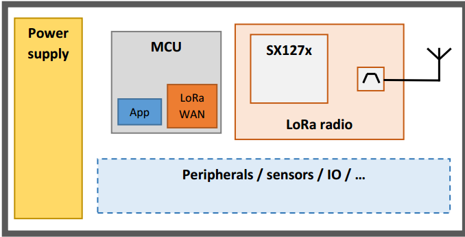 Figure 3. Design based on LoRa RF chipset.
Case 2: Design based on a LoRa module
A LoRa module means that the LoRa transceiver and an MCU are bound together (not in the same silicon package). This can be considered as a unit with all the connections between radio and MCU, plus antenna and other RF circuitry the vendor has already taken care of for the developer. For a developer, it means a board that contains a target MCU and RF transceiver integrated on the board (not on a chip). Arm Mbed OS provides the LoRaWAN stack and application, and the developer can modify the example application for his or her needs.
Case 3: Design based on a LoRa RF-MCU
An RF-MCU is an SoC including an MCU and LoRa transceiver on the same silicon package. From a developer’s point of view, this design is identical to a module-based design described in Case 2.
 Figure 4. Design based on LoRa module (both as integrated on board and on chip).
Case 4: Design based on a LoRa modem
A LoRa modem is a component that contains a stack and RF circuitry as a full package, mostly wired to a host MCU. In this case, if the developer wishes to be compliant with the existing applications, he or she may choose to write an adapter layer, which could be AT commands to control the modem.
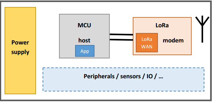 Figure 5. Design based on LoRa modem.
Please follow the detailed reference of LoRaWANInterface to understand what these APIs and related data structures mean and why are they designed in this way.
You must implement the initialize(events::EventQueue *queue) API. Our design philosophy is that we wish to support the tiniest of devices with very little memory, and an event queue shared between the application and network stack is the best option in terms of memory.
Testing
Note: We'll publish automated tests for LoRa soon. For Mbed Partners that want to start porting Lora drivers, please contact your Partner lead.