MAX5719BOB
MAX5719 Breakout Board - 20-bit, 0.05nV-sec DAC
Hello World
Import programMAX5719BOB_20bit_DAC
Maxim Integrated MAX5719 20-bit, 0.05nV-sec DAC Test program running on MAX32625MBED.
Last commit 03 Jan 2021 by ![]() Maxim Integrated
Maxim Integrated
Library
Import libraryMAX5719
Maxim Integrated MAX5719 20-bit, 0.05nV-sec DAC
Last commit 12 Jun 2021 by ![]() Maxim Integrated
Maxim Integrated
Pinout
Datasheet
http://www.maximintegrated.com/products/MAX5719BOBNotes
PRELIMINARY
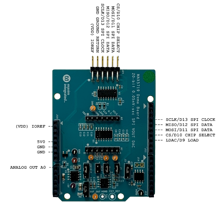
MAX5719 Breakout Board 20-bit, 0.05nV-sec DAC
General Description
Digital-to-analog converters (DACs) provide accurate output voltages for actuation and control in many electronic applications such as industrial, medical and RF systems. The MAX5719 is a highly accurate, 20-bit voltage output DAC featuring low glitch energy of 0.05nV-second. Development with DACs involves expertise in analog systems, power supplies, digital interfaces and firmware. Now, enter the MAX5719BOB to accelerate the development process.
The MAX5719BOB (Break Out Board) provides for rapid prototyping and development with the MAX5719 (a 20-bit, voltage-output DAC). MAX5719BOB interfaces to any Arduino™-compatible or mbed.org™ compatible platform system with expansion ports configurable for SPI communication. Additionally, the MAX5719BOB works with systems that have a Pmod™ connection, a 2x6 right-angle header at board edge (compatible with Digilentinc.com Pmod™ interface spec) Interface type 2A (expanded SPI) on 2x6 header at board edge. MAX5719 also comes with schematics, design files and firmware for immediate use and forking to future projects.
The board directly interfaces to SPI with logic levels in the range 3.0V to 5.5V. (Note: MAX5719 is specified for 4.5V to 5.5V operation)
The board comes installed with MAX5719AGSD+ installed.
Example firmware is provided for Arduino™ and mbed.org™ system boards.
Tested with:
- MAX32625MBED# https://os.mbed.com/platforms/MAX32625MBED/
- MAX32600MBED# https://os.mbed.com/platforms/MAX32600MBED/
- STM32F446 Nucleo-64 https://os.mbed.com/platforms/ST-Nucleo-F446RE/
- Arduino UNO (rev 3) https://store.arduino.cc/usa/arduino-uno-rev3/
- Adafruit Metro 328 Arduino compatible (USB micro B) https://www.adafruit.com/product/50
- Arduino Pro Mini 3.3V/8MHz https://store.arduino.cc/usa/arduino-pro-mini/
PMOD is a trademark of Digilent Inc
Arduino is a trademark of Arduino AG
Arm and Mbed are trademarks of Arm Limited (or its subsidiaries)
Windows is a trademark of Microsoft
Quick Start
Required Equipment
- MAX5719BOB# Breakout Board
- Appropriate mbed.org or Arduino board
- The procedures below describe the Quick Start process with the MAX32625MBED# and the Arduino UNO.
- Computer with USB and web access
- A serial terminal emulator software such as teraterm, realterm, picocom, minicom, or equivalent
The procedures below describe the Quick Start process with the MAX32625MBED# and the Arduino. MAX5719BOB has been tested on the platform boards listed above.
There are three example programs for each platform:
- The "Simplified Hello World" program is a small example program which can be changed by modifying the Hello_MAX5719.cpp source code and repeating the compile-build-upload cycle, providing straightforward code for easy adoption.
- The "Function Generator" program is a small example program which can be changed by modifying the FunctionGen_MAX5719.cpp source code and repeating the compile-build-upload cycle, providing straightforward code for easy adoption.
- The "Serial Tester" program is an interactive, menu-driven test program which is controlled through a serial communications port, using a terminal emulator, supporting quick discovery and evaluation of device features for testing functionality.
Procedure for Mbed: Simplified Hello World
The "Simplified Hello World" program is a small example program which can be changed by modifying the Hello_MAX5719.cpp source code and repeating the compile-build-upload cycle, providing straightforward code for easy adoption. The Breakout Board is fully assembled and tested. The first time the board is used, the MAX5719BOB firmware must be loaded into the MAX32625MBED, or equivalent platform board. This firmware is stored on the MAX32625MBED board and remains after the board is powered off. When the board is plugged into USB the first time, the computer may need about a minute to install its device drivers.
Import programMAX5719BOB_20bit_DAC
Maxim Integrated MAX5719 20-bit, 0.05nV-sec DAC Test program running on MAX32625MBED.
Last commit 03 Jan 2021 by ![]() Maxim Integrated
Maxim Integrated
Follow the steps below to verify board operation:
- Connect the MAX5719BOB to the MAX32625MBED or equivalent mbed platform board using the standard pinout.
- Connect a USB cable from computer to MAX32625MBED board “HDK” USB port. (Windows may require some time to install its device driver.) Expect the system to automatically mount the board as a new USB drive named MBED or DAPLINK or something similar. This is a special-purpose drive: firmware will be loaded into the board by copying the compiled binary into the board's drive. Don't write any other files to this drive.
- Open your board's USB device folder and double click on its MBED.HTML file. On the board page, click Add to your Mbed Compiler. This adds your Mbed board to the Online Compiler as a compilation target. See https://os.mbed.com/docs/mbed-os/v5.13/quick-start/index.html for more detailed instructions on using the online compiler.
- In a web browser, navigate to https://os.mbed.com/teams/MaximIntegrated/code/MAX5719BOB_20bit_DAC/ and click Import into Compiler. The mbed online IDE window opens, and prompts to import program. Click Import button to complete the import.
- Compile the program. When complete, the online mbed IDE downloads the firmware file to your local downloads folder.
- Locate the newly built firmware file MAX5719BOB_20bit_SPI_DAC.MAX32625MBED.bin and copy the file to the board's MBED drive. (The names might not match exactly if using a platform other than MAX32625MBED, or if there is already a file with that name.) If a warning dialog appears asking to move this file without its properties, answer yes. After file copying is complete, press and release the board's RESET button to start the firmware. Use a DVM to measure the voltages on the MAX5719BOB.
- The program behavior can be changed by modifying the Hello_MAX5719.cpp source code and repeating the compile-build-upload cycle from step 4.
- You can discard your local changes and reset to the latest published firmware version as follows: Bring up the project Revision tab and right-click on the line that says “default” “tip”. In the popup context menu, select Switch working copy to this revision…. There will be a warning that there are uncommitted local changes in the working tree. Click Discard, and all of the local files will be reset to the published version.
Procedure for Mbed: Function Generator
The "Function Generator" program is a small example program which can be changed by modifying the FunctionGen_MAX5719.cpp source code and repeating the compile-build-upload cycle, providing straightforward code for easy adoption. The Breakout Board is fully assembled and tested. The first time the board is used, the MAX5719BOB firmware must be loaded into the MAX32625MBED, or equivalent platform board. This firmware is stored on the MAX32625MBED board and remains after the board is powered off. When the board is plugged into USB the first time, the computer may need about a minute to install its device drivers.
Import programMAX5719BOB_FunctionGen
Maxim Integrated MAX5719 20-bit, 0.05nV-sec DAC Test program running on MAX32625MBED.
Last commit 03 Jan 2021 by ![]() Maxim Integrated
Maxim Integrated
Follow the steps below to verify board operation:
- Connect the MAX5719BOB to the MAX32625MBED or equivalent mbed platform board using the standard pinout.
- Connect a USB cable from computer to MAX32625MBED board “HDK” USB port. (Windows may require some time to install its device driver.) Expect the system to automatically mount the board as a new USB drive named MBED or DAPLINK or something similar. This is a special-purpose drive: firmware will be loaded into the board by copying the compiled binary into the board's drive. Don't write any other files to this drive.
- Open your board's USB device folder and double click on its MBED.HTML file. On the board page, click Add to your Mbed Compiler. This adds your Mbed board to the Online Compiler as a compilation target. See https://os.mbed.com/docs/mbed-os/v5.13/quick-start/index.html for more detailed instructions on using the online compiler.
- In a web browser, navigate to https://os.mbed.com/teams/MaximIntegrated/code/MAX5719BOB_FunctionGen/ and click Import into Compiler. The mbed online IDE window opens, and prompts to import program. Click Import button to complete the import.
- Compile the program. When complete, the online mbed IDE downloads the firmware file to your local downloads folder.
- Locate the newly built firmware file MAX5719BOB_FunctionGen.MAX32625MBED.bin and copy the file to the board's MBED drive. (The names might not match exactly if using a platform other than MAX32625MBED, or if there is already a file with that name.) If a warning dialog appears asking to move this file without its properties, answer yes. After file copying is complete, press and release the board's RESET button to start the firmware. Use an oscilloscope to measure the output waveform of the MAX5719BOB.
- The program behavior can be changed by modifying the FunctionGen_MAX5719.cpp source code and repeating the compile-build-upload cycle from step 4.
- You can discard your local changes and reset to the latest published firmware version as follows: Bring up the project Revision tab and right-click on the line that says “default” “tip”. In the popup context menu, select Switch working copy to this revision…. There will be a warning that there are uncommitted local changes in the working tree. Click Discard, and all of the local files will be reset to the published version.
Procedure for Mbed: Serial Tester
The "Serial Tester" program is an interactive, menu-driven test program which is controlled through a serial communications port, using a terminal emulator, supporting quick discovery and evaluation of device features for testing functionality.
The Breakout Board is fully assembled and tested. The first time the board is used, the MAX5719BOB firmware must be loaded into the MAX32625MBED, or equivalent platform board. This firmware is stored on the MAX32625MBED board and remains after the board is powered off. The serial tester firmware uses a USB serial port to communicate. When the board is plugged into USB the first time, the computer may need about a minute to install its device drivers.
Import programMAX5719BOB_Serial_Tester
Maxim Integrated MAX5719 20-bit, 0.05nV-sec DAC Test program running on MAX32625MBED. Control through USB Serial commands using a terminal emulator such as teraterm or putty.
Last commit 30 Jun 2021 by ![]() Maxim Integrated
Maxim Integrated
Follow the steps below to verify board operation:
- Connect the MAX5719BOB to the MAX32625MBED or equivalent mbed platform board using the standard pinout.
- Connect a USB cable from computer to MAX32625MBED board “HDK” USB port. (Windows may require some time to install its device driver.) Expect the system to automatically mount the board as a new USB drive named MBED or DAPLINK or something similar. This is a special-purpose drive: firmware will be loaded into the board by copying the compiled binary into the board's drive. Don't write any other files to this drive.
- Open your board's USB device folder and double click on its MBED.HTML file. On the board page, click Add to your Mbed Compiler. This adds your Mbed board to the Online Compiler as a compilation target. See https://os.mbed.com/docs/mbed-os/v5.13/quick-start/index.html for more detailed instructions on using the online compiler.
- In a web browser, navigate to https://os.mbed.com/teams/MaximIntegrated/code/MAX5719BOB_Serial_Tester/ and click Import into Compiler. The mbed online IDE window opens, and prompts to import program. Click Import button to complete the import.
- Compile the program. When complete, the online mbed IDE downloads the firmware file to your local downloads folder.
- Locate the newly built firmware file MAX5719BOB_Serial_Tester.MAX32625MBED.bin and copy the file to the board's MBED drive. (The names might not match exactly if using a platform other than MAX32625MBED, or if there is already a file with that name.) If a warning dialog appears asking to move this file without its properties, answer yes.
- Connect another, or the existing USB cable from computer to MAX32625MBED board “DEV” USB port. Expect the LEDs in the lower right corner should flash briefly and then remain lit.
- Locate the newly arrived USB Serial Device COM port, and use a serial terminal emulator (such as teraterm, realterm, picocom, minicom, or equivalent). Baud rate is 9600.
Procedure for Arduino: Simplified Hello World
The "Simplified Hello World" program is a small example program which can be changed by modifying the Hello_MAX5719.cpp source code and repeating the compile-build-upload cycle, providing straightforward code for easy adoption.
The Breakout Board is fully assembled and tested. Note if used with classic Arduino UNO which has full-sized USB type B connector, ensure that the shield of the USB connector does not contact the underside of the breakout board / Arduino shield. The first time the board is used, the MAX5719BOB firmware must be loaded into the Arduino board. This firmware is stored on the Arduino board and remains after the board is powered off. The firmware uses a USB serial port to communicate. When the board is plugged into USB the first time, the computer may need about a minute to install its device drivers.
Follow the steps below to verify board operation:
- Connect the MAX5719BOB to the Arduino board using the standard pinout.
- Connect a USB cable from computer to Arduino board USB port. (Windows may require some time to install its device driver.)
- In a web browser, navigate to https://create.arduino.cc/editor/whismanoid/88c84540-6947-4086-b660-1cf46af6bc3d/preview and click "Add to my Sketchbook".
- Connect USB cable to Arduino hardware. If first time using Arduino Create online, you may be prompted to install Arduino Create Agent to connect with the hardware.
- Compile the program with the "Upload and Save" button. Use a DVM to measure the voltages on the MAX5719BOB.
- The program behavior can be changed by modifying the Hello_MAX5719.cpp source code and repeating the compile-build-upload cycle.
Procedure for Arduino: Function Generator
The "Function Generator" program is a small example program which can be changed by modifying the FunctionGen_MAX5719.cpp source code and repeating the compile-build-upload cycle, providing straightforward code for easy adoption.
The Breakout Board is fully assembled and tested. Note if used with classic Arduino UNO which has full-sized USB type B connector, ensure that the shield of the USB connector does not contact the underside of the breakout board / Arduino shield. The first time the board is used, the MAX5719BOB firmware must be loaded into the Arduino board. This firmware is stored on the Arduino board and remains after the board is powered off. The firmware uses a USB serial port to communicate. When the board is plugged into USB the first time, the computer may need about a minute to install its device drivers.
Follow the steps below to verify board operation:
- Connect the MAX5719BOB to the Arduino board using the standard pinout.
- Connect a USB cable from computer to Arduino board USB port. (Windows may require some time to install its device driver.)
- In a web browser, navigate to https://create.arduino.cc/editor/whismanoid/2368936f-e3f9-4d16-b6ba-f2812856bc69/preview and click "Add to my Sketchbook".
- Connect USB cable to Arduino hardware. If first time using Arduino Create online, you may be prompted to install Arduino Create Agent to connect with the hardware.
- Compile the program with the "Upload and Save" button. Use an oscilloscope to measure the output waveform of the MAX5719BOB.
- The program behavior can be changed by modifying the FunctionGen_MAX5719.cpp source code and repeating the compile-build-upload cycle.
Procedure for Arduino: Serial Tester
The "Serial Tester" program is an interactive, menu-driven test program which is controlled through a serial communications port, using a terminal emulator, supporting quick discovery and evaluation of device features for testing functionality. The Breakout Board is fully assembled and tested. Note if used with classic Arduino UNO which has full-sized USB type B connector, ensure that the shield of the USB connector does not contact the underside of the breakout board / Arduino shield. The first time the board is used, the MAX5719BOB firmware must be loaded into the Arduino board. This firmware is stored on the Arduino board and remains after the board is powered off. The firmware uses a USB serial port to communicate. When the board is plugged into USB the first time, the computer may need about a minute to install its device drivers.
Follow the steps below to verify board operation:
- Connect the MAX5719BOB to the Arduino board using the standard pinout.
- Connect a USB cable from computer to Arduino board USB port. (Windows may require some time to install its device driver.)
- In a web browser, navigate to https://create.arduino.cc/editor/whismanoid/07b99e49-e148-4722-b9d2-3281e53b0038/preview and click "Add to my Sketchbook".
- Connect USB cable to Arduino hardware. If this is your first time using Arduino Create online, you may be prompted to install Arduino Create Agent to connect with the hardware.
- Compile the program with the "Upload and Save" button.
- Locate the newly arrived USB Serial Device COM port, and use a serial terminal emulator (such as teraterm, realterm, picocom, minicom, or equivalent). Baud rate is 9600.
Sending Commands with a Serial Console
A serial terminal emulator software (such as teraterm, realterm, putty, picocom, minicom, or equivalent) must be installed to communicate with the example firmware. Various terminal programs connect in various ways and have different user interfaces, but they all share a common set of basic features:
- Connecting to a specific serial port device by name, such as COM4 or /dev/ttyACM0
- Settings such as baud rate 9600, 8 bits / No parity / 1 Stop bit, no flow control
- Typing at the keyboard transmits to the firmware through the serial port
- Messages received from the firmware are displayed on the screen
- A special keyboard command or menu item exits the terminal program
See https://os.mbed.com/handbook/Terminals for more details. More resources:
- https://learn.sparkfun.com/tutorials/terminal-basics/tera-term-windows
- https://learn.sparkfun.com/tutorials/terminal-basics/real-term-windows
- https://learn.sparkfun.com/tutorials/terminal-basics/yat---yet-another-terminal-windows
- https://learn.sparkfun.com/tutorials/terminal-basics/coolterm-windows-mac-linux
- https://learn.adafruit.com/windows-tools-for-the-electrical-engineer/serial-terminal
- https://www.putty.org/
In Windows™, install a terminal emulator such as teraterm, realterm, or putty. Find the serial port name and COM port number in Control Panel “View devices and printers”. The Mbed board will appear as “USB Serial Device” or “mbed Serial Port”. See https://os.mbed.com/handbook/Windows-serial-configuration and https://os.mbed.com/docs/mbed-os/v5.11/tutorials/windows-serial-driver.html for troubleshooting. Start the terminal emulator and use the menu to connect to the serial port that belongs to the board. Pressing ENTER displays the firmware’s banner message (see example session).
In linux, install a terminal emulator such as minicom or picocom. For example, under Debian or Ubuntu linux, use
sudo apt-get install picocom
In linux (Debian), find the serial port name as follows:
# with the board not connected, get list of tty device names
ls -1 /dev/tty~* >dev_tty_baseline
# now connect the device to USB and find the new tty device name (such as /dev/ttyACM0)
ls -1 /dev/tty~* | diff dev_tty_baseline -
The picocom terminal emulator runs from the tty console. The tty device name must be given on the command line when starting picocom. See man picocom for more details.
picocom /dev/ttyACM0 --baud 9600
Pressing ENTER displays the firmware’s banner message (see example session). Pressing CTRL+A and then CTRL+X exits picocom.
Example Serial Console Session
The firmware uses a USB serial port to communicate. Typing “?” prints a menu of supported device commands.
Main menu MAX5719 20-bit 1-ch DAC [serial]
 ? -- help
MAX5719 > ?

Main menu MAX5719 20-bit 1-ch DAC [serial]
 ? -- help
 # -- lines beginning with # are comments
 . -- SelfTest
 %Hn {pin: 0 1 2 3 4 5 6 7 8 9 14 15 16 17} -- High Output
 %Ln {pin: 0 1 2 3 4 5 6 7 8 9 14 15 16 17} -- Low Output
 %?n {pin: 0 1 2 3 4 5 6 7 8 9 14 15 16 17} -- Input
 %A -- analogRead
 %SC SCLK=12000000=12.000MHz CPOL=0 CPHA=0 -- SPI config
 %SD -- SPI diagnostic messages hide
 %SW mosi,mosi,...mosi -- SPI write hex bytes
 A-Z,a-z,0-9 -- reserved for application use
 ! -- Init
 A code=? -- CODE
 B -- LOAD
 C code=? -- CODE_LOAD
 @ -- print MAX5719 configuration
 L -- LDACb output LH high LL low
MAX5719 > .
SelfTest()
      VRef = 4.096   MAX5719 20-bit LSB = 0.000004V = 3.90625uV
      Wire MAX5719 OUT to platform AIN0 for analog loopback tests...
+PASS MAX5719.VRef expect 4.096000
      0x000000 = 0.000V
      SPI MOSI-> 0x00 0x00 0x00 MISO<- 0x00 0x00 0x00
+PASS AIN0 =   0.391% = 0.023V   expect 0.000000 +/- 0.050000
      0x01f400 = 0.500V
      SPI MOSI-> 0x1F 0x40 0x00 MISO<- 0x00 0x00 0x00
+PASS AIN0 =   8.016% = 0.481V   expect 0.500000 +/- 0.050000
      0x03e800 = 1.000V
      SPI MOSI-> 0x3E 0x80 0x00 MISO<- 0x00 0x00 0x00
+PASS AIN0 =  15.934% = 0.956V   expect 1.000000 +/- 0.050000
      0x05dc00 = 1.500V
      SPI MOSI-> 0x5D 0xC0 0x00 MISO<- 0x00 0x00 0x00
+PASS AIN0 =  23.851% = 1.431V   expect 1.500000 +/- 0.075000
      0x07d000 = 2.000V
      SPI MOSI-> 0x7D 0x00 0x00 MISO<- 0x00 0x00 0x00
+PASS AIN0 =  31.769% = 1.906V   expect 2.000000 +/- 0.100000
      0x09c400 = 2.500V
      SPI MOSI-> 0x9C 0x40 0x00 MISO<- 0x00 0x00 0x00
+PASS AIN0 =  39.687% = 2.381V   expect 2.500000 +/- 0.150000
      0x0bb800 = 3.000V
      SPI MOSI-> 0xBB 0x80 0x00 MISO<- 0x00 0x00 0x00
+PASS AIN0 =  47.507% = 2.850V   expect 3.000000 +/- 0.200000
      0x0dac00 = 3.500V
      SPI MOSI-> 0xDA 0xC0 0x00 MISO<- 0x00 0x00 0x00
+PASS AIN0 =  55.327% = 3.320V   expect 3.500000 +/- 0.250000
      0x0fa000 = 4.000V
      SPI MOSI-> 0xFA 0x00 0x00 MISO<- 0x00 0x00 0x00
+PASS AIN0 =  59.238% = 3.554V   expect 4.000000 +/- 0.500000
      0x0fffff = 4.095V
      SPI MOSI-> 0xFF 0xFF 0xF0 MISO<- 0x00 0x00 0x00
+PASS AIN0 =  59.335% = 3.560V   expect 4.095000 +/- 0.750000
      SPI MOSI-> 0x80 0x00 0x00 MISO<- 0x00 0x00 0x00
+PASS AIN0 =  32.551% = 1.953V   expect 2.048000 +/- 0.200000
      VRef = 4.096   MAX5719 20-bit LSB = 0.000004V = 3.90625uV
      test_voltage_sweep V = 0.000000V to 4.096000V precision 0.100000V step 0.500000V
+PASS MAX5719.DACCodeOfVoltage(0.0000V) expect 0
+PASS MAX5719.DACCodeOfVoltage(0.5000V) expect 128000
+PASS MAX5719.DACCodeOfVoltage(1.0000V) expect 256000
+PASS MAX5719.DACCodeOfVoltage(1.5000V) expect 384000
+PASS MAX5719.DACCodeOfVoltage(2.0000V) expect 512000
+PASS MAX5719.DACCodeOfVoltage(2.5000V) expect 640000
+PASS MAX5719.DACCodeOfVoltage(3.0000V) expect 768000
+PASS MAX5719.DACCodeOfVoltage(3.5000V) expect 896000
+PASS MAX5719.DACCodeOfVoltage(4.0000V) expect 1024000
      test_voltage_sweep V = -0.010000V to 0.100000V precision 0.010000V step 0.010000V
+PASS MAX5719.DACCodeOfVoltage(-0.0100V) expect 0
+PASS MAX5719.DACCodeOfVoltage(0.0000V) expect 0
+PASS MAX5719.DACCodeOfVoltage(0.0100V) expect 2560
+PASS MAX5719.DACCodeOfVoltage(0.0200V) expect 5120
+PASS MAX5719.DACCodeOfVoltage(0.0300V) expect 7680
+PASS MAX5719.DACCodeOfVoltage(0.0400V) expect 10240
+PASS MAX5719.DACCodeOfVoltage(0.0500V) expect 12800
+PASS MAX5719.DACCodeOfVoltage(0.0600V) expect 15360
+PASS MAX5719.DACCodeOfVoltage(0.0700V) expect 17920
+PASS MAX5719.DACCodeOfVoltage(0.0800V) expect 20480
+PASS MAX5719.DACCodeOfVoltage(0.0900V) expect 23040
+PASS MAX5719.DACCodeOfVoltage(0.1000V) expect 25600
      test_voltage_sweep V = 2.047900V to 2.048100V precision 0.000010V step 0.000010V
+PASS MAX5719.DACCodeOfVoltage(2.0479V) expect 524260
+PASS MAX5719.DACCodeOfVoltage(2.0479V) expect 524262
+PASS MAX5719.DACCodeOfVoltage(2.0479V) expect 524265
+PASS MAX5719.DACCodeOfVoltage(2.0479V) expect 524268
+PASS MAX5719.DACCodeOfVoltage(2.0479V) expect 524270
+PASS MAX5719.DACCodeOfVoltage(2.0479V) expect 524273
+PASS MAX5719.DACCodeOfVoltage(2.0480V) expect 524275
+PASS MAX5719.DACCodeOfVoltage(2.0480V) expect 524278
+PASS MAX5719.DACCodeOfVoltage(2.0480V) expect 524280
+PASS MAX5719.DACCodeOfVoltage(2.0480V) expect 524283
+PASS MAX5719.DACCodeOfVoltage(2.0480V) expect 524285
+PASS MAX5719.DACCodeOfVoltage(2.0480V) expect 524288
+PASS MAX5719.DACCodeOfVoltage(2.0480V) expect 524291
+PASS MAX5719.DACCodeOfVoltage(2.0480V) expect 524293
+PASS MAX5719.DACCodeOfVoltage(2.0480V) expect 524296
+PASS MAX5719.DACCodeOfVoltage(2.0480V) expect 524298
+PASS MAX5719.DACCodeOfVoltage(2.0480V) expect 524301
+PASS MAX5719.DACCodeOfVoltage(2.0481V) expect 524303
+PASS MAX5719.DACCodeOfVoltage(2.0481V) expect 524306
+PASS MAX5719.DACCodeOfVoltage(2.0481V) expect 524308
+PASS MAX5719.DACCodeOfVoltage(2.0481V) expect 524311
+PASS MAX5719.DACCodeOfVoltage(2.0481V) expect 524314
      test_voltage_sweep V = 3.996000V to 4.106000V precision 0.010000V step 0.010000V
+PASS MAX5719.DACCodeOfVoltage(3.9900V) expect 1021440
+PASS MAX5719.DACCodeOfVoltage(4.0000V) expect 1024000
+PASS MAX5719.DACCodeOfVoltage(4.0100V) expect 1026560
+PASS MAX5719.DACCodeOfVoltage(4.0200V) expect 1029120
+PASS MAX5719.DACCodeOfVoltage(4.0300V) expect 1031680
+PASS MAX5719.DACCodeOfVoltage(4.0400V) expect 1034240
+PASS MAX5719.DACCodeOfVoltage(4.0500V) expect 1036800
+PASS MAX5719.DACCodeOfVoltage(4.0600V) expect 1039360
+PASS MAX5719.DACCodeOfVoltage(4.0700V) expect 1041920
+PASS MAX5719.DACCodeOfVoltage(4.0800V) expect 1044480
+PASS MAX5719.DACCodeOfVoltage(4.0900V) expect 1047040
+PASS MAX5719.DACCodeOfVoltage(4.1000V) expect 1048575
      test_lsb_sweep V = 4.096000V LSBradius = 3LSB
+PASS MAX5719.DACCodeOfVoltage(4.0960V) expect 1048573
+PASS MAX5719.DACCodeOfVoltage(4.0960V) expect 1048573
+PASS MAX5719.DACCodeOfVoltage(4.0960V) expect 1048574
+PASS MAX5719.DACCodeOfVoltage(4.0960V) expect 1048574
+PASS MAX5719.DACCodeOfVoltage(4.0960V) expect 1048575
+PASS MAX5719.DACCodeOfVoltage(4.0960V) expect 1048575
+PASS MAX5719.DACCodeOfVoltage(4.0960V) expect 1048575
+PASS MAX5719.DACCodeOfVoltage(4.0960V) expect 1048575
+PASS MAX5719.DACCodeOfVoltage(4.0960V) expect 1048575
+PASS MAX5719.DACCodeOfVoltage(4.0960V) expect 1048575
+PASS MAX5719.DACCodeOfVoltage(4.0960V) expect 1048575
+PASS MAX5719.DACCodeOfVoltage(4.0960V) expect 1048575
+PASS MAX5719.DACCodeOfVoltage(4.0960V) expect 1048575
      test_lsb_sweep V = 3.072000V LSBradius = 3LSB
+PASS MAX5719.DACCodeOfVoltage(3.0720V) expect 786429
+PASS MAX5719.DACCodeOfVoltage(3.0720V) expect 786429
+PASS MAX5719.DACCodeOfVoltage(3.0720V) expect 786430
+PASS MAX5719.DACCodeOfVoltage(3.0720V) expect 786430
+PASS MAX5719.DACCodeOfVoltage(3.0720V) expect 786431
+PASS MAX5719.DACCodeOfVoltage(3.0720V) expect 786431
+PASS MAX5719.DACCodeOfVoltage(3.0720V) expect 786432
+PASS MAX5719.DACCodeOfVoltage(3.0720V) expect 786433
+PASS MAX5719.DACCodeOfVoltage(3.0720V) expect 786433
+PASS MAX5719.DACCodeOfVoltage(3.0720V) expect 786434
+PASS MAX5719.DACCodeOfVoltage(3.0720V) expect 786434
+PASS MAX5719.DACCodeOfVoltage(3.0720V) expect 786435
+PASS MAX5719.DACCodeOfVoltage(3.0720V) expect 786435
      test_lsb_sweep V = 2.048000V LSBradius = 3LSB
+PASS MAX5719.DACCodeOfVoltage(2.0480V) expect 524285
+PASS MAX5719.DACCodeOfVoltage(2.0480V) expect 524285
+PASS MAX5719.DACCodeOfVoltage(2.0480V) expect 524286
+PASS MAX5719.DACCodeOfVoltage(2.0480V) expect 524286
+PASS MAX5719.DACCodeOfVoltage(2.0480V) expect 524287
+PASS MAX5719.DACCodeOfVoltage(2.0480V) expect 524287
+PASS MAX5719.DACCodeOfVoltage(2.0480V) expect 524288
+PASS MAX5719.DACCodeOfVoltage(2.0480V) expect 524289
+PASS MAX5719.DACCodeOfVoltage(2.0480V) expect 524289
+PASS MAX5719.DACCodeOfVoltage(2.0480V) expect 524290
+PASS MAX5719.DACCodeOfVoltage(2.0480V) expect 524290
+PASS MAX5719.DACCodeOfVoltage(2.0480V) expect 524291
+PASS MAX5719.DACCodeOfVoltage(2.0480V) expect 524291
      test_lsb_sweep V = 1.024000V LSBradius = 3LSB
+PASS MAX5719.DACCodeOfVoltage(1.0240V) expect 262141
+PASS MAX5719.DACCodeOfVoltage(1.0240V) expect 262141
+PASS MAX5719.DACCodeOfVoltage(1.0240V) expect 262142
+PASS MAX5719.DACCodeOfVoltage(1.0240V) expect 262142
+PASS MAX5719.DACCodeOfVoltage(1.0240V) expect 262143
+PASS MAX5719.DACCodeOfVoltage(1.0240V) expect 262143
+PASS MAX5719.DACCodeOfVoltage(1.0240V) expect 262144
+PASS MAX5719.DACCodeOfVoltage(1.0240V) expect 262145
+PASS MAX5719.DACCodeOfVoltage(1.0240V) expect 262145
+PASS MAX5719.DACCodeOfVoltage(1.0240V) expect 262146
+PASS MAX5719.DACCodeOfVoltage(1.0240V) expect 262146
+PASS MAX5719.DACCodeOfVoltage(1.0240V) expect 262147
+PASS MAX5719.DACCodeOfVoltage(1.0240V) expect 262147
      test_lsb_sweep V = 0.000000V LSBradius = 3LSB
+PASS MAX5719.DACCodeOfVoltage(-0.0000V) expect 0
+PASS MAX5719.DACCodeOfVoltage(-0.0000V) expect 0
+PASS MAX5719.DACCodeOfVoltage(-0.0000V) expect 0
+PASS MAX5719.DACCodeOfVoltage(-0.0000V) expect 0
+PASS MAX5719.DACCodeOfVoltage(-0.0000V) expect 0
+PASS MAX5719.DACCodeOfVoltage(-0.0000V) expect 0
+PASS MAX5719.DACCodeOfVoltage(0.0000V) expect 0
+PASS MAX5719.DACCodeOfVoltage(0.0000V) expect 1
+PASS MAX5719.DACCodeOfVoltage(0.0000V) expect 1
+PASS MAX5719.DACCodeOfVoltage(0.0000V) expect 2
+PASS MAX5719.DACCodeOfVoltage(0.0000V) expect 2
+PASS MAX5719.DACCodeOfVoltage(0.0000V) expect 3
+PASS MAX5719.DACCodeOfVoltage(0.0000V) expect 3
Summary: 132 PASS 0 FAIL

MAX5719 > C code=0x80000
CODE_LOAD dacCodeLsbs=524288

      SPI MOSI-> 0x80 0x00 0x00 MISO<- 0x00 0x00 0x00  =1

MAX5719 > C code=0x12345
CODE_LOAD dacCodeLsbs=74565

      SPI MOSI-> 0x12 0x34 0x50 MISO<- 0x00 0x00 0x00  =1

MAX5719 > A code=0xfffff
CODE dacCodeLsbs=1048575

      SPI MOSI-> 0xFF 0xFF 0xF0 MISO<- 0x00 0x00 0x00  =1

MAX5719 > B
LOAD =1

MAX5719 > @
VRef = 4.096000
DACCode = 1048575 = 0x000fffff

MAX5719 >
Detailed Description of Hardware
The MAX5719 is a 20-bit, voltage-output DAC with SPI Interface. The MAX6126 provides a 4.096V reference voltage. For bipolar operation, the MAX889 charge pump generates a -5V power supply rail to drive the MAX44264 operational amplifier. Jumpers JUNIBIP, JBIP, JBUF, and J4 select unipolar or bipolar output configuration, and jumpers J1 and J3 select on-board 4.096V reference or external reference configuration. When configured for buffered unipolar or bipolar output, analog output is driven from the BUF_OUT test point. When configured for direct unipolar output, analog output is driven from the OUT test point. The analog output pin OUT is also connected to the standard Arduino A0 analog pin on the external connector, with Schottky diodes D1 clamping the voltage to avoid exceeding the Arduino or mbed board’s IOREF voltage rail. For more information on these products, please visit:
- www.maximintegrated.com/max5719
- www.maximintegrated.com/max889
- www.maximintegrated.com/max44264
- www.maximintegrated.com/max6126
- www.maximintegrated.com/max14850
Bipolar (-5V to 5V) Wiring Connection
To drive an output in the range -5V to 5V, put the J4 shunt on pins 1-2, JUNIBIP shunt on 2-3 (BIP), JBUF shunt on 1-2, and JBIP shunt on 1-2. and connect BUF_OUT test point to the positive side of the load. Connect the ground return side of the load to the GND test point.
Unipolar (0 to 5V) Wiring Connection
To drive an output in the range 0 to 5V, put the J4 shunt on pins 2-3 (the MAX889 charge pump and MAX44264 op amp and resistors R3-R4 will not be used). Put the JUNIBIP shunt on 1-2 (UNI), JBUF shunt on 1-2, and no shunt on JBIP. Connect BUF_OUT test point to the positive side of the load. Connect the ground return side of the load to the GND test point.
Minimal Component Count (0 to 4.096VREF) Wiring Connection
To drive an output in the range 0 to 4.096VREF with minimal component count, remove the shunts from J4, JBUF, JUNIBIP, and JBIP (the MAX889 charge pump and MAX44264 op amp and resistors R1-R4 will not be used). Connect OUT pin of the MAX5719 to the positive side of the load. Connect the ground return side of the load to the GND test point. Leave all other test points unconnected.
Table 1. Jumper Functions
| Jumper | State | Function |
|---|---|---|
| J14 | 1-2* | +4.096VREF reference force/sense connection point |
| J3 | 1-2* | +4.096VREF reference drives MAX5719 REFF input |
| 2-3 | External reference EXT_REFIN drives MAX5719 REFF input | |
| J1 | 1-2* | +4.096VREF reference drives MAX5719 REFS input |
| Open | External reference EXT_REFIN drives MAX5719 REFS input | |
| JBUF | 1-2* | MAX5719 OUT drives noninverting input of MAX44246 op amp buffer; load is connected to BUF_OUT test point |
| Open | MAX44264 op amp is not used; load is connected to OUT test point | |
| JBIP | 1-2 | Bipolar configuration: RFB input senses BUF_OUT |
| Open* | Unipolar configuration: RFB is not connected | |
| JUNIBIP | 1-2* | Unipolar configuration: MAX44246 is configured as unity-gain buffer |
| 2-3 | Bipolar configuration: MAX44264 inverting input is driven by INV; use with JBIP=1-2 so that RFB input senses BUF_OUT | |
| J4 | 1-2* | Op amp dual supply +/-5V using charge pump U5 MAX889 |
| 2-3 | Op amp single supply 5V; charge pump is not used |
*Default
Ordering Information
| PART | TYPE |
|---|---|
| MAX5719BOB# | Breakout Board |
#Denotes RoHS compliant.
You need to log in to post a discussion
Board Partner
Maxim Integrated
Maxim's microcontrollers provide low-power, efficient, and secure solutions for challenging embedded applications.


