MAX5171BOB
MAX5171 Breakout Board - 14-bit Force/Sense DAC
Hello World
Import programMAX5171BOB_14bit_Remote_Sense_SPI_DAC
Example host software for the Maxim Integrated MAX5171 14-bit Force/Sense DAC. Hosted on the MAX32625MBED.
Last commit 15 May 2020 by ![]() Maxim Integrated
Maxim Integrated
Library
Import libraryMAX5171
Maxim Integrated MAX5171 14-bit Force/Sense DAC
Last commit 15 May 2020 by ![]() Maxim Integrated
Maxim Integrated
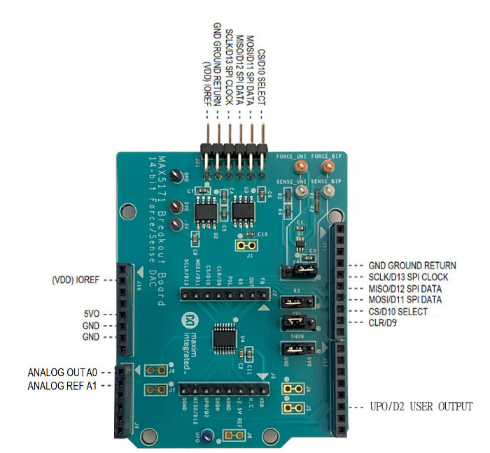
Pinout
Datasheet
http://www.maximintegrated.com/products/MAX5171BOBNotes
PRELIMINARY
MAX5171 Breakout Board 14-bit Force/Sense DAC
General Description
Digital-to-analog converters (DACs) provide accurate output voltages for actuation and control in many electronic applications such as industrial, medical and RF systems. The MAX5171 is a highly accurate, 14-bit voltage output DAC. Development with DACs involves expertise in analog systems, power supplies, digital interfaces and firmware. Now, enter the MAX5171BOB to accelerate the development process.
The MAX5171BOB (Break Out Board) provides for rapid prototyping and development with the MAX5171 (a 14-bit, voltage-output DAC). MAX5171BOB interfaces to any Arduino™-compatible or mbed.org™ compatible platform system with expansion ports configurable for SPI communication. Additionally, the MAX5171BOB works with systems that have a Pmod™ connection, a 2x6 right-angle header at board edge (compatible with Digilentinc.com Pmod™ interface spec) Interface type 2A (expanded SPI) on 2x6 header at board edge. MAX5171 also comes with schematics, design files and firmware for immediate use and forking to future projects.
The board directly interfaces to SPI with logic levels in the range 2.7V to 5.5V. (Note: MAX5171 is specified for 4.5V to 5.5V operation, and the pin-compatible MAX5173 is specified for 2.7V to 3.6V operation.)
The board comes installed with MAX5171AEEE+ installed.
Example firmware is provided for Arduino™ and mbed.org™ system boards.
Tested with:
- MAX32625MBED# https://os.mbed.com/platforms/MAX32625MBED/
- MAX32600MBED# https://os.mbed.com/platforms/MAX32600MBED/
- STM32F446 Nucleo-64 https://os.mbed.com/platforms/ST-Nucleo-F446RE/
- Arduino UNO (rev 3) https://store.arduino.cc/usa/arduino-uno-rev3/
- Adafruit Metro 328 Arduino compatible (USB micro B) https://www.adafruit.com/product/50
- Arduino Pro Mini 3.3V/8MHz https://store.arduino.cc/usa/arduino-pro-mini/
PMOD is a trademark of Digilent Inc
Arduino is a trademark of Arduino AG
Arm and Mbed are trademarks of Arm Limited (or its subsidiaries)
Windows is a trademark of Microsoft
Quick Start
Required Equipment
- MAX5171BOB# Breakout Board
- Appropriate mbed.org or Arduino board
- The procedures below describe the Quick Start process with the MAX32625MBED# and the Arduino UNO.
- Computer with USB and web access
- A serial terminal emulator software such as teraterm, realterm, picocom, minicom, or equivalent
The procedures below describe the Quick Start process with the MAX32625MBED# and the Arduino. MAX5171BOB has been tested on the platform boards listed above.
There are two example programs for each platform:
- The "Simplified Hello World" program is a small example program which can be changed by modifying the Hello_MAX5171.cpp source code and repeating the compile-build-upload cycle, providing straightforward code for easy adoption.
- The "Serial Tester" program is an interactive, menu-driven test program which is controlled through a serial communications port, using a terminal emulator, supporting quick discovery and evaluation of device features for testing functionality.
Procedure for Mbed: Simplified Hello World
The "Simplified Hello World" program is a small example program which can be changed by modifying the Hello_MAX5171.cpp source code and repeating the compile-build-upload cycle, providing straightforward code for easy adoption. The Breakout Board is fully assembled and tested. The first time the board is used, the MAX5171BOB firmware must be loaded into the MAX32625MBED or equivalent platform board. This firmware is stored on the MAX32625MBED board and remains after the board is powered off. When the board is plugged into USB the first time, the computer may need about a minute to install its device drivers.
Import programMAX5171BOB_14bit_Remote_Sense_SPI_DAC
Example host software for the Maxim Integrated MAX5171 14-bit Force/Sense DAC. Hosted on the MAX32625MBED.
Last commit 15 May 2020 by ![]() Maxim Integrated
Maxim Integrated
Follow the steps below to verify board operation:
- Connect the MAX5171BOB to the MAX32625MBED or equivalent mbed platform board using the standard pinout.
- Connect a USB cable from computer to MAX32625MBED board “HDK” USB port. (Windows may require some time to install its device driver.) Expect the system to automatically mount the board as a new USB drive named MBED or DAPLINK or something similar. This is a special-purpose drive: firmware will be loaded into the board by copying the compiled binary into the board's drive. Don't write any other files to this drive.
- Open your board's USB device folder and double click on its MBED.HTML file. On the board page, click Add to your Mbed Compiler. This adds your Mbed board to the Online Compiler as a compilation target. See https://os.mbed.com/docs/mbed-os/v5.13/quick-start/index.html for more detailed instructions on using the online compiler.
- In a web browser, navigate to https://os.mbed.com/teams/MaximIntegrated/code/MAX5171BOB_14bit_Remote_Sense_SPI_DAC/ and click Import into Compiler. The mbed online IDE window opens, and prompts to import program. Click Import button to complete the import.
- Compile the program. When complete, the online mbed IDE downloads the firmware file to your local downloads folder.
- Locate the newly built firmware file MAX5171BOB_14bit_Remote_Sense_SPI_DAC.MAX32625MBED.bin and copy the file to the board's MBED drive. (The names might not match exactly if using a platform other than MAX32625MBED, or if there is already a file with that name.) If a warning dialog appears asking to move this file without its properties, answer yes. After file copying is complete, press and release the board's RESET button to start the firmware. Use a DVM to measure the voltages on the MAX5171BOB.
- The program behavior can be changed by modifying the Hello_MAX5171.cpp source code and repeating the compile-build-upload cycle from step 4.
- You can discard your local changes and reset to the latest published firmware version as follows: Bring up the project Revision tab and right-click on the line that says “default” “tip”. In the popup context menu, select Switch working copy to this revision…. There will be a warning that there are uncommitted local changes in the working tree. Click Discard, and all of the local files will be reset to the published version.
Procedure for Mbed: Serial Tester
The "Serial Tester" program is an interactive, menu-driven test program which is controlled through a serial communications port, using a terminal emulator, supporting quick discovery and evaluation of device features for testing functionality.
The Breakout Board is fully assembled and tested. The first time the board is used, the MAX5171BOB firmware must be loaded into the MAX32625MBED, or equivalent platform board. This firmware is stored on the MAX32625MBED board and remains after the board is powered off. The serial tester firmware uses a USB serial port to communicate. When the board is plugged into USB the first time, the computer may need about a minute to install its device drivers.
Import programMAX5171BOB_Serial_Tester
Test program running on MAX32625MBED. Control through USB Serial commands using a terminal emulator such as teraterm or putty.
Last commit 15 May 2020 by ![]() Maxim Integrated
Maxim Integrated
Follow the steps below to verify board operation:
- Connect the MAX5171BOB to the MAX32625MBED or equivalent mbed platform board using the standard pinout.
- Connect a USB cable from computer to MAX32625MBED board “HDK” USB port. (Windows may require some time to install its device driver.) Expect the system to automatically mount the board as a new USB drive named MBED or DAPLINK or something similar. This is a special-purpose drive: firmware will be loaded into the board by copying the compiled binary into the board's drive. Don't write any other files to this drive.
- Open your board's USB device folder and double click on its MBED.HTML file. On the board page, click Add to your Mbed Compiler. This adds your Mbed board to the Online Compiler as a compilation target. See https://os.mbed.com/docs/mbed-os/v5.13/quick-start/index.html for more detailed instructions on using the online compiler.
- In a web browser, navigate to https://os.mbed.com/teams/MaximIntegrated/code/MAX5171BOB_Serial_Tester/ and click Import into Compiler. The mbed online IDE window opens, and prompts to import program. Click Import button to complete the import.
- Compile the program. When complete, the online mbed IDE downloads the firmware file to your local downloads folder.
- Locate the newly built firmware file MAX5171BOB_Serial_Tester.MAX32625MBED.bin and copy the file to the board's MBED drive. (The names might not match exactly if using a platform other than MAX32625MBED, or if there is already a file with that name.) If a warning dialog appears asking to move this file without its properties, answer yes.
- Connect another, or the existing USB cable from computer to MAX32625MBED board “DEV” USB port. Expect the LEDs in the lower right corner should flash briefly and then remain lit.
- Locate the newly arrived USB Serial Device COM port, and use a serial terminal emulator (such as teraterm, realterm, picocom, minicom, or equivalent). Baud rate is 9600.
Procedure for Arduino: Simplified Hello World
The "Simplified Hello World" program is a small example program which can be changed by modifying the Hello_MAX5171.cpp source code and repeating the compile-build-upload cycle, providing straightforward code for easy adoption. The Breakout Board is fully assembled and tested. Note if used with classic Arduino UNO which has full-sized USB type B connector, ensure that the shield of the USB connector does not contact the underside of the breakout board / Arduino shield. The first time the board is used, the MAX5171BOB firmware must be loaded into the Arduino board. This firmware is stored on the Arduino board and remains after the board is powered off. The firmware uses a USB serial port to communicate. When the board is plugged into USB the first time, the computer may need about a minute to install its device drivers.
Follow the steps below to verify board operation:
- Connect the MAX5171BOB to the Arduino board using the standard pinout.
- Connect a USB cable from computer to Arduino board USB port. (Windows may require some time to install its device driver.)
- In a web browser, navigate to https://create.arduino.cc/editor/whismanoid/10d1ee33-1599-4c0a-aeec-6d4be4091929/preview and click "Add to my Sketchbook".
- Connect USB cable to Arduino hardware. If first time using Arduino Create online, you may be prompted to install Arduino Create Agent to connect with the hardware.
- Compile the program with the "Upload and Save" button.
- The program behavior can be changed by modifying the Hello_MAX5171.cpp source code and repeating the compile-build-upload cycle.
Procedure for Arduino: Serial Tester
The "Serial Tester" program is an interactive, menu-driven test program which is controlled through a serial communications port, using a terminal emulator, supporting quick discovery and evaluation of device features for testing functionality.
The Breakout Board is fully assembled and tested. Note if used with classic Arduino UNO which has full-sized USB type B connector, ensure that the shield of the USB connector does not contact the underside of the breakout board / Arduino shield. The first time the board is used, the MAX5171BOB firmware must be loaded into the Arduino board. This firmware is stored on the Arduino board and remains after the board is powered off. The firmware uses a USB serial port to communicate. When the board is plugged into USB the first time, the computer may need about a minute to install its device drivers.
Follow the steps below to verify board operation:
- Connect the MAX5171BOB to the Arduino board using the standard pinout.
- Connect a USB cable from computer to Arduino board USB port. (Windows may require some time to install its device driver.)
- In a web browser, navigate to https://create.arduino.cc/editor/whismanoid/8ed60c93-04d2-4b08-b2ab-7289dade5f8c/preview and click "Add to my Sketchbook".
- Connect USB cable to Arduino hardware. If this is your first time using Arduino Create online, you may be prompted to install Arduino Create Agent to connect with the hardware.
- Compile the program with the "Upload and Save" button.
- Locate the newly arrived USB Serial Device COM port, and use a serial terminal emulator (such as teraterm, realterm, picocom, minicom, or equivalent). Baud rate is 9600.
Sending Commands with a Serial Console
A serial terminal emulator software (such as teraterm, realterm, putty, picocom, minicom, or equivalent) must be installed to communicate with the example firmware. Various terminal programs connect in various ways and have different user interfaces, but they all share a common set of basic features:
- Connecting to a specific serial port device by name, such as COM4 or /dev/ttyACM0
- Settings such as baud rate 9600, 8 bits / No parity / 1 Stop bit, no flow control
- Typing at the keyboard transmits to the firmware through the serial port
- Messages received from the firmware are displayed on the screen
- A special keyboard command or menu item exits the terminal program
See https://os.mbed.com/handbook/Terminals for more details. More resources:
- https://learn.sparkfun.com/tutorials/terminal-basics/tera-term-windows
- https://learn.sparkfun.com/tutorials/terminal-basics/real-term-windows
- https://learn.sparkfun.com/tutorials/terminal-basics/yat---yet-another-terminal-windows
- https://learn.sparkfun.com/tutorials/terminal-basics/coolterm-windows-mac-linux
- https://learn.adafruit.com/windows-tools-for-the-electrical-engineer/serial-terminal
- https://www.putty.org/
In Windows™, install a terminal emulator such as teraterm, realterm, or putty. Find the serial port name and COM port number in Control Panel “View devices and printers”. The Mbed board will appear as “USB Serial Device” or “mbed Serial Port”. See https://os.mbed.com/handbook/Windows-serial-configuration and https://os.mbed.com/docs/mbed-os/v5.11/tutorials/windows-serial-driver.html for troubleshooting. Start the terminal emulator and use the menu to connect to the serial port that belongs to the board. Pressing ENTER displays the firmware’s banner message (see example session).
In linux, install a terminal emulator such as minicom or picocom. For example, under Debian or Ubuntu linux, use
sudo apt-get install picocom
In linux (Debian), find the serial port name as follows:
# with the board not connected, get list of tty device names
ls -1 /dev/tty~* >dev_tty_baseline
# now connect the device to USB and find the new tty device name (such as /dev/ttyACM0)
ls -1 /dev/tty~* | diff dev_tty_baseline -
The picocom terminal emulator runs from the tty console. The tty device name must be given on the command line when starting picocom. See man picocom for more details.
picocom /dev/ttyACM0 --baud 9600
Pressing ENTER displays the firmware’s banner message (see example session). Pressing CTRL+A and then CTRL+X exits picocom.
Example Serial Console Session
The firmware uses a USB serial port to communicate. Typing “?” prints a menu of supported device commands.
Main menu MAX5171 14-bit Force/Sense DAC [serial]
 ? -- help
MAX5171 > # Example for MAX5171 Breakout Board

Main menu MAX5171 14-bit Force/Sense DAC [serial]
 ? -- help
MAX5171 > ?

Main menu MAX5171 14-bit Force/Sense DAC [serial]
 ? -- help
 # -- lines beginning with # are comments
 . -- SelfTest
 %Hn {pin: 0 1 2 3 4 5 6 7 8 9 14 15 16 17} -- High Output
 %Ln {pin: 0 1 2 3 4 5 6 7 8 9 14 15 16 17} -- Low Output
 %?n {pin: 0 1 2 3 4 5 6 7 8 9 14 15 16 17} -- Input
 %A -- analogRead
 %SC SCLK=24000000=24.000MHz CPOL=0 CPHA=0 -- SPI config
 %SD -- SPI diagnostic messages hide
 %SW mosi,mosi,...mosi -- SPI write hex bytes
 A-Z,a-z,0-9 -- reserved for application use
 ! -- Init
 0 code=? -- CODE
 4 code=? -- CODE_LOAD
 8 -- LOAD
 c -- NOP
 d -- SHUTDOWN
 e0 -- UPO_LOW
 e8 -- UPO_HIGH
 f0 -- MODE1_DOUT_SCLK_RISING_EDGE
 f8 -- MODE0_DOUT_SCLK_FALLING_EDGE
 @ -- print MAX5171 configuration
MAX5171 > # send 4 CODE_LOAD code=0x3fff expect AIN0(AIN4)=full scale 2.5V

Main menu MAX5171 14-bit Force/Sense DAC [serial]
 ? -- help
MAX5171 > 4 code=0x3fff
CODE_LOAD dacCodeLsbs=16383

      SPI MOSI-> 0x7F 0xFF MISO<- 0x00 0x00  =1

MAX5171 > # send 4 CODE_LOAD code=0x0000 expect AIN0(AIN4)=zero scale 0V

Main menu MAX5171 14-bit Force/Sense DAC [serial]
 ? -- help
MAX5171 > 4 code=0x0000
CODE_LOAD dacCodeLsbs=0

      SPI MOSI-> 0x40 0x00 MISO<- 0x7F 0xFF  =1

MAX5171 > # send 4 CODE_LOAD code=0x1fff expect AIN0(AIN4)=mid scale 1.25V

Main menu MAX5171 14-bit Force/Sense DAC [serial]
 ? -- help
MAX5171 > 4 code=0x1fff
CODE_LOAD dacCodeLsbs=8191

      SPI MOSI-> 0x5F 0xFF MISO<- 0x40 0x00  =1

MAX5171 > # send e8 UPO_HIGH expect input D2=1

Main menu MAX5171 14-bit Force/Sense DAC [serial]
 ? -- help
MAX5171 > e8
UPO_HIGH
      SPI MOSI-> 0xE8 0x00 MISO<- 0x5F 0xFF  =1

MAX5171 > # send e0 UPO_LOW expect input D2=0

Main menu MAX5171 14-bit Force/Sense DAC [serial]
 ? -- help
MAX5171 > e0
UPO_LOW
      SPI MOSI-> 0xE0 0x00 MISO<- 0xE8 0x00  =1

MAX5171 > .
SelfTest()
      VRef = 2.500  MAX5171 14-bit LSB = 0.00015V
+PASS MAX5171.DACCodeOfVoltage(2.4998V) expect 16383
+PASS MAX5171.DACCodeOfVoltage(2.4997V) expect 16382
+PASS MAX5171.DACCodeOfVoltage(2.4995V) expect 16381
+PASS MAX5171.DACCodeOfVoltage(2.4994V) expect 16380
+PASS MAX5171.DACCodeOfVoltage(1.2502V) expect 8193
+PASS MAX5171.DACCodeOfVoltage(1.2500V) expect 8192
+PASS MAX5171.DACCodeOfVoltage(1.2498V) expect 8191
+PASS MAX5171.DACCodeOfVoltage(1.2497V) expect 8190
+PASS MAX5171.DACCodeOfVoltage(0.0005V) expect 3
+PASS MAX5171.DACCodeOfVoltage(0.0003V) expect 2
+PASS MAX5171.DACCodeOfVoltage(0.0002V) expect 1
+PASS MAX5171.DACCodeOfVoltage(0.0000V) expect 0
      VRef = 2.500  MAX5171 14-bit LSB = 0.00015V
+PASS MAX5171.VoltageOfCode(0x3fff) expect 2.499847
+PASS MAX5171.VoltageOfCode(0x3ffe) expect 2.499695
+PASS MAX5171.VoltageOfCode(0x3ffd) expect 2.499542
+PASS MAX5171.VoltageOfCode(0x3ffc) expect 2.499390
+PASS MAX5171.VoltageOfCode(0x2001) expect 1.250153
+PASS MAX5171.VoltageOfCode(0x2000) expect 1.250000
+PASS MAX5171.VoltageOfCode(0x1fff) expect 1.249847
+PASS MAX5171.VoltageOfCode(0x1ffe) expect 1.249695
+PASS MAX5171.VoltageOfCode(0x3) expect 0.000458
+PASS MAX5171.VoltageOfCode(0x2) expect 0.000305
+PASS MAX5171.VoltageOfCode(0x1) expect 0.000153
+PASS MAX5171.VoltageOfCode(0x0) expect 0.000000
+PASS MAX5171.VRef expect 2.500000
# 0% of full scale REF(2.50V) = 2.50V Jumper FB=1-2
      SPI MOSI-> 0x7F 0xFF MISO<- 0xE0 0x00
+PASS AIN0 =  41.740% = 2.504V   expect 2.500000 +/- 0.050000
# 0% of full scale REF(2.50V) = 0.000V
      SPI MOSI-> 0x40 0x00 MISO<- 0x7F 0xFF
+PASS AIN0 =   0.391% = 0.023V   expect 0.000000 +/- 0.050000
# 0% of full scale REF(2.50V) = 1.25V
      SPI MOSI-> 0x5F 0xFF MISO<- 0x40 0x00
+PASS AIN0 =  21.017% = 1.261V   expect 1.250000 +/- 0.050000
      SPI MOSI-> 0xE8 0x00 MISO<- 0x5F 0xFF
+PASS UPO signal=1 UPO_pin is high after MAX5171 UPO_HIGH command
      SPI MOSI-> 0xE0 0x00 MISO<- 0xE8 0x00
!WARN expected UPO signal=0 UPO_pin is low after MAX5171 UPO_LOW command, but got actual UPO=1, missing UPO connections?
      SPI MOSI-> 0xE8 0x00 MISO<- 0xE0 0x00
+PASS UPO signal=1 UPO_pin is high after MAX5171 UPO_HIGH command
Summary: 30 PASS 0 FAIL

MAX5171 >
Detailed Description of Hardware
The MAX5171 is a 14-bit, voltage-output DAC with SPI Interface. The MAX6126 provides a 2.5V reference voltage. For bipolar operation, the MAX889 charge pump generates a -5V power supply rail to drive the MAX44260 operational amplifier. Jumper FB selects unipolar or bipolar output configuration. When configured for unipolar output, analog output is driven from the FORCE_UNI test point and sensed by the SENSE_UNI test point, with closed-loop feedback through resistor network R1-R2. When configured for bipolar output, analog output is driven from the FORCE_BIP test point and sensed by the SENSE_BIP test point, with closed-loop feedback through resistor network R3-R4. (The analog output pin OUT is also connected to the standard Arduino A0 analog pin on the external connector.) For more information on these products, please visit:
- www.maximintegrated.com/max5171
- www.maximintegrated.com/max5173
- www.maximintegrated.com/max889
- www.maximintegrated.com/max44260
- www.maximintegrated.com/max6126
Bipolar (-5V to 5V) Force/Sense Wiring Connection
To drive an output in the range -5V to 5V, put the FB shunt on pins 1-2, and connect both the FORCE_BIP and SENSE_BIP test points to the positive side of the load. Connect the ground return side of the load to the GND test point. Leave the FORCE_UNI and SENSE_UNI test points unconnected. For best accuracy, avoid the resistive (I x R) voltage drop losses in the supply wire by using two separate wires for FORCE and SENSE.
Unipolar (0 to 5V) Force/Sense Wiring Connection
To drive an output in the range 0 to 5V, put the FB shunt on pins 2-3 (the MAX889 charge pump and MAX44260 op amp and resistors R3-R4 will not be used). Connect both the FORCE_UNI and SENSE_UNI test points to the positive side of the load. Connect the ground return side of the load to the GND test point. Leave the FORCE_BIP and SENSE_BIP test points unconnected. For best accuracy, avoid the resistive (I x R) voltage drop losses in the supply wire by using two separate wires for FORCE and SENSE.
Minimal Component Count (0 to 2.5V) Force/Sense Wiring Connection
To drive an output in the range 0 to 2.5V with minimal component count, remove the FB shunt (the MAX889 charge pump and MAX44260 op amp and resistors R1-R4 will not be used). Connect both the OUT and FB pins of the MAX5171 to the positive side of the load. Connect the ground return side of the load to the GND test point. Leave all other test points unconnected. For best accuracy, avoid the resistive (I x R) voltage drop losses in the supply wire by using two separate wires for OUT and FB.
Evaluating the 2.7V to 3.6V MAX5173
The MAX5173 is the pin-compatible low-voltage version of MAX5171, specified for 2.7V to 3.6V operation. All on-board support circuitry (MAX889 charge pump, MAX44260 operational amplifier, and MAX6126 voltage reference) are specified to operate over the full 2.7V to 5.5V range. For specified operation of MAX5173, replace U3 with a 1.25V reference such as the pin-compatible MAX6190AESA+.
Table 1. Jumper Functions
| Jumper | State | Function |
|---|---|---|
| PDL | 1-2 * | PDL = logic high: shutdown function is allowed. |
| 2-3 | PDL = logic low: shutdown function is disabled. | |
| RS | 1-2 | RS = logic high: output will be midscale at reset. |
| 2-3* | RS = logic low: output will be zero at reset. | |
| SHDN | 1-2 | SHDN = logic high: MAX5171 is shut down. |
| 2-3* | SHDN = logic low: normal operation. | |
| FB | 1-2* (BIP) | Bipolar output configuration (+5V/-5V): connect positive terminal of load to FORCE_BIP and SENSE_BIP test points. |
| 2-3 (UNI) | Unipolar output configuration (+5V): connect positive terminal of load to FORCE_UNI and SENSE_UNI test points. | |
| J7 | 1-2* | Analog reference REF connects to Arduino pin A1 |
| J6 | 1-2* | Analog output OUT connects to Arduino pin A0 |
| J4 | 1-2* | VDD supply is driven by Arduino IOREF supply |
| J8 | 1-2* | User Programmable Output UPO connects to Arduino pin D2 |
| J1 | 1-2* | 2.5V reference force/sense connection point |
| J5 | 1-2* | 2.5V reference drives MAX5171 REF input |
*Default
Ordering Information
| PART | TYPE |
|---|---|
| MAX5171BOB# | Breakout Board |
#Denotes RoHS compliant.
You need to log in to post a discussion

Board Partner
Maxim Integrated
Maxim's microcontrollers provide low-power, efficient, and secure solutions for challenging embedded applications.


