MAX11410BOB
MAX11410 Breakout Board - 24-bit 1.9ksps Delta-Sigma ADC
Hello World
Import programMAX11410BOB_24bit_ADC
MAX11410 is a high speed, 24-bit Delta-Sigma ADC; small example program which can be changed by modifying the Hello_MAX11410.cpp source code and repeating the compile-build-upload cycle, providing straightforward code for easy adoption.
Last commit 27 Oct 2020 by ![]() Maxim Integrated
Maxim Integrated
Library
Import libraryMAX11410
MAX11410 high speed 24-bit Delta-Sigma ADC
Last commit 27 Oct 2020 by ![]() Maxim Integrated
Maxim Integrated
Pinout
Datasheet
http://www.maximintegrated.com/products/MAX11410BOBNotes
PRELIMINARY
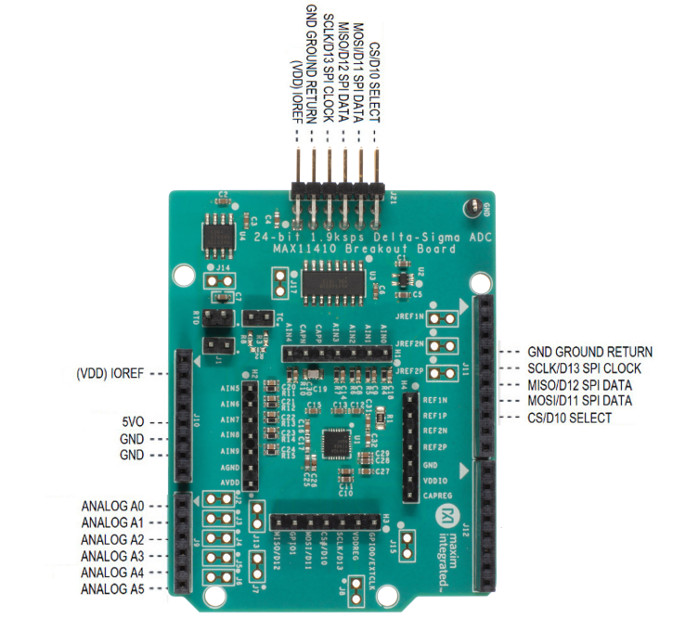
MAX11410 Breakout Board 24-bit 1.9ksps Delta-Sigma ADC
General Description
Analog-to-digital converters (ADCs) provide accurate measurement and conversion of signals to digital format for sensing in many electronic applications such as industrial, medical and sensor systems. The MAX11410 is a high speed, 24-bit Delta-Sigma ADC. Development with Delta-Sigma ADCs involves expertise in analog systems, power supplies, digital interfaces and firmware. Now, enter the MAX11410BOB to accelerate the development process.
The MAX11410BOB Breakout Board provides for rapid prototyping and development with the MAX11410 (a 24-bit, 1.9ksps, Delta-Sigma ADC). MAX11410BOB interfaces to any Arduino™-compatible or mbed.org™ compatible platform system with expansion ports configurable for SPI communication. Additionally, the MAX11410BOB works with systems that have a Pmod™ connection, a 2x6 right-angle header at board edge (compatible with Digilentinc.com Pmod™ interface spec) Interface type 2A (expanded SPI) on 2x6 header at board edge. MAX11410 also comes with schematics, design files, and firmware for immediate use and forking to future projects.
The board interfaces to SPI with logic levels in the range 1.71V to 5.5V.
The board comes installed with MAX11410ATI+ installed.
Example firmware is provided for Arduino™ and mbed.org™ system boards.
Tested with:
- MAX32625MBED# https://os.mbed.com/platforms/MAX32625MBED/
- MAX32600MBED# https://os.mbed.com/platforms/MAX32600MBED/
- STM32F446 Nucleo-64 https://os.mbed.com/platforms/ST-Nucleo-F446RE/
- Arduino UNO (rev 3) https://store.arduino.cc/usa/arduino-uno-rev3/
- Adafruit Metro 328 Arduino compatible (USB micro B) https://www.adafruit.com/product/50
- Arduino Pro Mini 3.3V/8MHz https://store.arduino.cc/usa/arduino-pro-mini/
PMOD is a trademark of Digilent Inc
Arduino is a trademark of Arduino AG
Arm and Mbed are trademarks of Arm Limited (or its subsidiaries)
Windows is a trademark of Microsoft
Quick Start
Required Equipment
- MAX11410BOB# Breakout Board
- Appropriate mbed.org or Arduino board
- The procedures below describe the Quick Start process with the MAX32625MBED# and the Arduino UNO.
- Computer with USB and web access
- A serial terminal emulator software such as teraterm, realterm, picocom, minicom, or equivalent
The procedures below describe the Quick Start process with the MAX32625MBED# and the Arduino. MAX11410BOB has been tested on the platform boards listed above.
There are two example programs for each platform:
- The "Simplified Hello World" program is a small example program which can be changed by modifying the Hello_MAX11410.cpp source code and repeating the compile-build-upload cycle, providing straightforward code for easy adoption.
- The "Serial Tester" program is an interactive, menu-driven test program which is controlled through a serial communications port, using a terminal emulator, supporting quick discovery and evaluation of device features for testing functionality.
Procedure for Mbed: Simplified Hello World
The "Simplified Hello World" program is a small example program which can be changed by modifying the Hello_MAX11410.cpp source code and repeating the compile-build-upload cycle, providing straightforward code for easy adoption. The Breakout Board is fully assembled and tested. The first time the board is used, the MAX11410BOB firmware must be loaded into the MAX32625MBED, or equivalent platform board. This firmware is stored on the MAX32625MBED board and remains after the board is powered off. When the board is plugged into USB the first time, the computer may need about a minute to install its device drivers.
Import programMAX11410BOB_24bit_ADC
MAX11410 is a high speed, 24-bit Delta-Sigma ADC; small example program which can be changed by modifying the Hello_MAX11410.cpp source code and repeating the compile-build-upload cycle, providing straightforward code for easy adoption.
Last commit 27 Oct 2020 by ![]() Maxim Integrated
Maxim Integrated
Follow the steps below to verify board operation:
- Connect the MAX11410BOB to the MAX32625MBED or equivalent mbed platform board using the standard pinout.
- Connect a USB cable from computer to MAX32625MBED board “HDK” USB port. (Windows may require some time to install its device driver.) Expect the system to automatically mount the board as a new USB drive named MBED or DAPLINK or something similar. This is a special-purpose drive: firmware will be loaded into the board by copying the compiled binary into the board's drive. Don't write any other files to this drive.
- Open your board's USB device folder and double click on its MBED.HTML file. On the board page, click Add to your Mbed Compiler. This adds your Mbed board to the Online Compiler as a compilation target. See https://os.mbed.com/docs/mbed-os/v5.13/quick-start/index.html for more detailed instructions on using the online compiler.
- In a web browser, navigate to https://os.mbed.com/teams/MaximIntegrated/code/MAX11410BOB_24bit_ADC/ and click Import into Compiler. The mbed online IDE window opens, and prompts to import program. Click Import button to complete the import.
- Compile the program. When complete, the online mbed IDE downloads the firmware file to your local downloads folder.
- Locate the newly built firmware file MAX11410BOB_24bit_ADC.MAX32625MBED.bin and copy the file to the board's MBED drive. (The names might not match exactly if using a platform other than MAX32625MBED, or if there is already a file with that name.) If a warning dialog appears asking to move this file without its properties, answer yes. After file copying is complete, press and release the board's RESET button to start the firmware. Connect input voltages to AIN inputs. Note: if nothing is connected to the analog inputs, the value may "float" to an unspecified, arbitrary value.
- The program behavior can be changed by modifying the Hello_MAX11410.cpp source code and repeating the compile-build-upload cycle from step 4.
- You can discard your local changes and reset to the latest published firmware version as follows: Bring up the project Revision tab and right-click on the line that says “default” “tip”. In the popup context menu, select Switch working copy to this revision…. There will be a warning that there are uncommitted local changes in the working tree. Click Discard, and all of the local files will be reset to the published version.
Procedure for Mbed: Serial Tester
The "Serial Tester" program is an interactive, menu-driven test program which is controlled through a serial communications port, using a terminal emulator, supporting quick discovery and evaluation of device features for testing functionality.
The Breakout Board is fully assembled and tested. The first time the board is used, the MAX11410BOB firmware must be loaded into the MAX32625MBED, or equivalent platform board. This firmware is stored on the MAX32625MBED board and remains after the board is powered off. The serial tester firmware uses a USB serial port to communicate. When the board is plugged into USB the first time, the computer may need about a minute to install its device drivers.
Import programMAX11410BOB_Serial_Tester
Test program running on MAX32625MBED. Control through USB Serial commands using a terminal emulator such as teraterm or putty.
Last commit 27 Oct 2020 by ![]() Maxim Integrated
Maxim Integrated
Follow the steps below to verify board operation:
- Connect the MAX11410BOB to the MAX32625MBED or equivalent mbed platform board using the standard pinout.
- Connect a USB cable from computer to MAX32625MBED board “HDK” USB port. (Windows may require some time to install its device driver.) Expect the system to automatically mount the board as a new USB drive named MBED or DAPLINK or something similar. This is a special-purpose drive: firmware will be loaded into the board by copying the compiled binary into the board's drive. Don't write any other files to this drive.
- Open your board's USB device folder and double click on its MBED.HTML file. On the board page, click Add to your Mbed Compiler. This adds your Mbed board to the Online Compiler as a compilation target. See https://os.mbed.com/docs/mbed-os/v5.13/quick-start/index.html for more detailed instructions on using the online compiler.
- In a web browser, navigate to https://os.mbed.com/teams/MaximIntegrated/code/MAX11410BOB_Serial_Tester/ and click Import into Compiler. The mbed online IDE window opens, and prompts to import program. Click Import button to complete the import.
- Compile the program. When complete, the online mbed IDE downloads the firmware file to your local downloads folder.
- Locate the newly built firmware file MAX11410BOB_Serial_Tester.MAX32625MBED.bin and copy the file to the board's MBED drive. (The names might not match exactly if using a platform other than MAX32625MBED, or if there is already a file with that name.) If a warning dialog appears asking to move this file without its properties, answer yes.
- Connect another, or the existing USB cable from computer to MAX32625MBED board “DEV” USB port. Expect the LEDs in the lower right corner should flash briefly and then remain lit.
- Locate the newly arrived USB Serial Device COM port, and use a serial terminal emulator (such as teraterm, realterm, picocom, minicom, or equivalent). Baud rate is 9600.
Procedure for Arduino: Simplified Hello World
The "Simplified Hello World" program is a small example program which can be changed by modifying the Hello_MAX11410.cpp source code and repeating the compile-build-upload cycle, providing straightforward code for easy adoption.
The Breakout Board is fully assembled and tested. Note if used with classic Arduino UNO which has full-sized USB type B connector, ensure that the shield of the USB connector does not contact the underside of the breakout board / Arduino shield. The first time the board is used, the MAX11410BOB firmware must be loaded into the Arduino board. This firmware is stored on the Arduino board and remains after the board is powered off. The firmware uses a USB serial port to communicate. When the board is plugged into USB the first time, the computer may need about a minute to install its device drivers.
Follow the steps below to verify board operation:
- Connect the MAX11410BOB to the Arduino board using the standard pinout.
- Connect a USB cable from computer to Arduino board USB port. (Windows may require some time to install its device driver.)
- In a web browser, navigate to https://create.arduino.cc/editor/whismanoid/88dd946b-d8be-45ef-b922-aa1dfd13d1af/preview and click "Add to my Sketchbook".
- Connect USB cable to Arduino hardware. If this is your first time using Arduino Create online, you may be prompted to install Arduino Create Agent to connect with the hardware.
- Compile the program with the "Upload and Save" button.
- Connect input voltages to AIN inputs. Note: if nothing is connected to the analog inputs, the value may "float" to an unspecified, arbitrary value.
- The program behavior can be changed by modifying the Hello_MAX11410.cpp source code and repeating the compile-build-upload cycle.
Procedure for Arduino: Serial Tester
The "Serial Tester" program is an interactive, menu-driven test program which is controlled through a serial communications port, using a terminal emulator, supporting quick discovery and evaluation of device features for testing functionality.
The Breakout Board is fully assembled and tested. Note if used with classic Arduino UNO which has full-sized USB type B connector, ensure that the shield of the USB connector does not contact the underside of the breakout board / Arduino shield. The first time the board is used, the MAX11410BOB firmware must be loaded into the Arduino board. This firmware is stored on the Arduino board and remains after the board is powered off. The firmware uses a USB serial port to communicate. When the board is plugged into USB the first time, the computer may need about a minute to install its device drivers.
Follow the steps below to verify board operation:
- Connect the MAX11410BOB to the Arduino board using the standard pinout.
- Connect a USB cable from computer to Arduino board USB port. (Windows may require some time to install its device driver.)
- In a web browser, navigate to https://create.arduino.cc/editor/whismanoid/4a982b95-bb92-4ca3-99f8-3029b693a119/preview and click "Add to my Sketchbook".
- Connect USB cable to Arduino hardware. If this is your first time using Arduino Create online, you may be prompted to install Arduino Create Agent to connect with the hardware.
- Compile the program with the "Upload and Save" button.
- Locate the newly arrived USB Serial Device COM port, and use a serial terminal emulator (such as teraterm, realterm, picocom, minicom, or equivalent). Baud rate is 9600.
Sending Commands with a Serial Console
A serial terminal emulator software (such as teraterm, realterm, putty, picocom, minicom, or equivalent) must be installed to communicate with the example firmware. Various terminal programs connect in various ways and have different user interfaces, but they all share a common set of basic features:
- Connecting to a specific serial port device by name, such as COM4 or /dev/ttyACM0
- Settings such as baud rate 9600, 8 bits / No parity / 1 Stop bit, no flow control
- Typing at the keyboard transmits to the firmware through the serial port
- Messages received from the firmware are displayed on the screen
- A special keyboard command or menu item exits the terminal program
See https://os.mbed.com/handbook/Terminals for more details. More resources:
- https://learn.sparkfun.com/tutorials/terminal-basics/tera-term-windows
- https://learn.sparkfun.com/tutorials/terminal-basics/real-term-windows
- https://learn.sparkfun.com/tutorials/terminal-basics/yat---yet-another-terminal-windows
- https://learn.sparkfun.com/tutorials/terminal-basics/coolterm-windows-mac-linux
- https://learn.adafruit.com/windows-tools-for-the-electrical-engineer/serial-terminal
- https://www.putty.org/
In Windows™, install a terminal emulator such as teraterm, realterm, or putty. Find the serial port name and COM port number in Control Panel “View devices and printers”. The Mbed board will appear as “USB Serial Device” or “mbed Serial Port”. See https://os.mbed.com/handbook/Windows-serial-configuration and https://os.mbed.com/docs/mbed-os/v5.11/tutorials/windows-serial-driver.html for troubleshooting. Start the terminal emulator and use the menu to connect to the serial port that belongs to the board. Pressing ENTER displays the firmware’s banner message (see example session).
In linux, install a terminal emulator such as minicom or picocom. For example, under Debian or Ubuntu linux, use
sudo apt-get install picocom
In linux (Debian), find the serial port name as follows:
# with the board not connected, get list of tty device names
ls -1 /dev/tty~* >dev_tty_baseline
# now connect the device to USB and find the new tty device name (such as /dev/ttyACM0)
ls -1 /dev/tty~* | diff dev_tty_baseline -
The picocom terminal emulator runs from the tty console. The tty device name must be given on the command line when starting picocom. See man picocom for more details.
picocom /dev/ttyACM0 --baud 9600
Pressing ENTER displays the firmware’s banner message (see example session). Pressing CTRL+A and then CTRL+X exits picocom.
Example Serial Console Session
The firmware uses a USB serial port to communicate. Typing “?” prints a menu of supported device commands.
# Brief Example for MAX11410BOB Breakout Board

Main menu MAX11410 24-bit 1.9ksps Delta-Sigma ADC [serial]
 ? -- help
MAX11410 > ?

Main menu MAX11410 24-bit 1.9ksps Delta-Sigma ADC [serial]
 ? -- help
 # -- lines beginning with # are comments
 . -- SelfTest
 %Hn {pin: 0 1 2 3 4 5 6 7 8 9 14 15 16 17} -- High Output
 %Ln {pin: 0 1 2 3 4 5 6 7 8 9 14 15 16 17} -- Low Output
 %?n {pin: 0 1 2 3 4 5 6 7 8 9 14 15 16 17} -- Input
 %A -- analogRead
 %SC SCLK=8000000=8.000MHz CPOL=0 CPHA=0 -- SPI config
 %SD -- SPI diagnostic messages hide
 %SW mosi,mosi,...mosi -- SPI write hex bytes
 A-Z,a-z,0-9 -- reserved for application use
 ! -- Init
 $ -- Read_All_Voltages
 R  -- Measure_RTD
 T  -- Measure_Thermocouple
 V  -- Measure_Voltage
 X0 -- Calibrate_Self_Offset_Gain
 X1 -- Calibrate_PGA_Gain
 XC extclk=? u_bn=? format=? refbufp_en=? refbufn_en=? ref_sel=? -- Configure_CTRL
 XF linef=? rate=? -- Configure_FILTER
 XI idac1_sel=? idac0_sel=? -- Configure_MUX_CTRL1
 XM ainp=? ainn=? -- Configure_MUX_CTRL0
 XP sigpath=? gain=? -- Configure_PGA
 XR ref_sel=? -- Configure_CTRL_REF
 XS vbias_mode=? brn_mode=? idac_mode=? -- Configure_SOURCE
 XV vbias_ain7_ain0_bitmap=? -- Configure_MUX_CTRL2
 @ -- print MAX11410 configuration
 ~* -- read core registers
 ~*regname? -- read register
 ~*regname=regvalue -- write register
 01 23 45 67 89 ab cd ef -- write and read raw hex codes
MAX11410 > ~*
 scan RegName...
PD=0x000000
CONV_START=0x000001
SEQ_START=0x00003a
CAL_START=0x000000
GP0_CTRL=0x0000c4
GP1_CTRL=0x0000c4
GP_CONV=0x000000
GP_SEQ_ADDR=0x00003a
FILTER=0x000034
CTRL=0x000002
SOURCE=0x00000b
MUX_CTRL0=0x00002a
MUX_CTRL1=0x0000ff
MUX_CTRL2=0x000000
PGA=0x000000
WAIT_EXT=0x000000
WAIT_START=0x000000

MAX11410 > R
Measure_RTD rtd_iout=7 rtd_ainp=8 rtd_ainn=9 Measure_RTD

      SPI MOSI-> 0x08 0x34 MISO<- 0xFF 0xFF
      SPI MOSI-> 0x09 0x00 MISO<- 0xFF 0xFF
      SPI MOSI-> 0x0A 0x0B MISO<- 0xFF 0xFF
      SPI MOSI-> 0x0B 0x89 MISO<- 0xFF 0xFF
      SPI MOSI-> 0x0C 0xF7 MISO<- 0xFF 0xFF
      SPI MOSI-> 0x0E 0x21 MISO<- 0xFF 0xFF
      SPI MOSI-> 0x05 0xC3 MISO<- 0xFF 0xFF
      SPI MOSI-> 0x05 0xC4 MISO<- 0xFF 0xFF
      SPI MOSI-> 0x01 0x01 MISO<- 0xFF 0xFF
      SPI MOSI-> 0xB0 0x00 0x00 0x00 MISO<- 0xFF 0xFF 0xFE 0xF5
      SPI MOSI-> 0xB8 0x00 0x00 0x00 MISO<- 0xFF 0x00 0x00 0x00
      SPI MOSI-> 0xB8 0x00 0x00 0x00 MISO<- 0xFF 0x00 0x00 0x00
      SPI MOSI-> 0xB8 0x00 0x00 0x00 MISO<- 0xFF 0x00 0x00 0x00
      SPI MOSI-> 0xB8 0x00 0x00 0x00 MISO<- 0xFF 0x00 0x00 0x00
      SPI MOSI-> 0xB8 0x00 0x00 0x00 MISO<- 0xFF 0x00 0x00 0x00
      SPI MOSI-> 0xB8 0x00 0x00 0x00 MISO<- 0xFF 0x00 0x00 0x00
      SPI MOSI-> 0xB8 0x00 0x00 0x00 MISO<- 0xFF 0x00 0x00 0x00
      SPI MOSI-> 0xB8 0x00 0x00 0x00 MISO<- 0xFF 0x00 0x00 0x00
      SPI MOSI-> 0xB8 0x00 0x00 0x00 MISO<- 0xFF 0x00 0x00 0x00
      SPI MOSI-> 0xB8 0x00 0x00 0x00 MISO<- 0xFF 0x00 0x00 0x00
      SPI MOSI-> 0xB8 0x00 0x00 0x00 MISO<- 0xFF 0x00 0x00 0x00
      SPI MOSI-> 0xB8 0x00 0x00 0x00 MISO<- 0xFF 0x00 0x00 0x00
      SPI MOSI-> 0xB8 0x00 0x00 0x00 MISO<- 0xFF 0x00 0x00 0x00
      SPI MOSI-> 0xB8 0x00 0x00 0x00 MISO<- 0xFF 0x00 0x00 0x00
      SPI MOSI-> 0xB8 0x00 0x00 0x00 MISO<- 0xFF 0x00 0x00 0x00
      SPI MOSI-> 0xB8 0x00 0x00 0x00 MISO<- 0xFF 0x01 0x00 0x10
      SPI MOSI-> 0xB0 0x00 0x00 0x00 MISO<- 0xFF 0x7F 0xFF 0xFF
      SPI MOSI-> 0x0C 0xFF MISO<- 0xFF 0xFF  =1.250000
rtd_ohm=1.250000
rtd_degc=-243.878942

MAX11410 > V ainp=2
Measure_Voltage ainp=2 ainn=10 Measure_Voltage

      SPI MOSI-> 0x0B 0x2A MISO<- 0xFF 0xFF
      SPI MOSI-> 0x09 0x02 MISO<- 0xFF 0xFF
      SPI MOSI-> 0x0E 0x00 MISO<- 0xFF 0xFF
      SPI MOSI-> 0x08 0x34 MISO<- 0xFF 0xFF
      SPI MOSI-> 0x01 0x01 MISO<- 0xFF 0xFF
      SPI MOSI-> 0xB0 0x00 0x00 0x00 MISO<- 0xFF 0x7F 0xFF 0xFF
      SPI MOSI-> 0xB8 0x00 0x00 0x00 MISO<- 0xFF 0x00 0x00 0x00
      SPI MOSI-> 0xB8 0x00 0x00 0x00 MISO<- 0xFF 0x00 0x00 0x00
      SPI MOSI-> 0xB8 0x00 0x00 0x00 MISO<- 0xFF 0x00 0x00 0x10
      SPI MOSI-> 0xB0 0x00 0x00 0x00 MISO<- 0xFF 0xFF 0xFE 0xFE  =-0.000077

MAX11410 > %SD

MAX11410 > V ainp-2  =2
Measure_Voltage ainp=2 ainn=10 Measure_Voltage
 =-0.000083

MAX11410 > $
Read_All_Voltages =1
AINcode[0]=4383421 = 0x0042e2bd
AINcode[1]=2787149 = 0x002a874d
AINcode[2]=16776922 = 0x00fffeda
AINcode[3]=16776952 = 0x00fffef8
AINcode[4]=475880 = 0x000742e8
AINcode[5]=16776922 = 0x00fffeda
AINcode[6]=461652 = 0x00070b54
AINcode[7]=16776921 = 0x00fffed9
AINcode[8]=16776945 = 0x00fffef1
AINcode[9]=16776918 = 0x00fffed6
AINcode[10]=8388607 = 0x007fffff

MAX11410 > @
ref0_v = 2.500000
ref1_v = 4999.000000
ref2_v = 2.500000
avdd_v = 3.300000
ctrl = 2 = 0x00000002
pgaGain = 1 = 0x01
status = 65552 = 0x00010010
data0 = 8388607 = 0x007fffff
AINcode[0] = 4383421 = 0x0042e2bd
AINcode[1] = 2787149 = 0x002a874d
AINcode[2] = 16776922 = 0x00fffeda
AINcode[3] = 16776952 = 0x00fffef8
AINcode[4] = 475880 = 0x000742e8
AINcode[5] = 16776922 = 0x00fffeda
AINcode[6] = 461652 = 0x00070b54
AINcode[7] = 16776921 = 0x00fffed9
AINcode[8] = 16776945 = 0x00fffef1
AINcode[9] = 16776918 = 0x00fffed6
AINcode[10] = 8388607 = 0x007fffff
loop_limit = 3000 = 0x0bb8
rtd_ms = 100
rtd_ohm = 1.250000
rtd_degc = -243.878942
rtd_filter = 52 = 0x34
rtd_ctrl = 0 = 0x00
rtd_source = 11
rtd_pga = 33 = 0x21
tc_v = 0.000000
tc_delta_degc = 0.000000
tc_degc = 0.000000

MAX11410 > @ ref0+v  _v=1.25
ref0_v = 1.250000
ref1_v = 4999.000000
ref2_v = 2.500000
avdd_v = 3.300000
ctrl = 2 = 0x00000002
pgaGain = 1 = 0x01
status = 65552 = 0x00010010
data0 = 8388607 = 0x007fffff
AINcode[0] = 4383421 = 0x0042e2bd
AINcode[1] = 2787149 = 0x002a874d
AINcode[2] = 16776922 = 0x00fffeda
AINcode[3] = 16776952 = 0x00fffef8
AINcode[4] = 475880 = 0x000742e8
AINcode[5] = 16776922 = 0x00fffeda
AINcode[6] = 461652 = 0x00070b54
AINcode[7] = 16776921 = 0x00fffed9
AINcode[8] = 16776945 = 0x00fffef1
AINcode[9] = 16776918 = 0x00fffed6
AINcode[10] = 8388607 = 0x007fffff
loop_limit = 3000 = 0x0bb8
rtd_ms = 100
rtd_ohm = 1.250000
rtd_degc = -243.878942
rtd_filter = 52 = 0x34
rtd_ctrl = 0 = 0x00
rtd_source = 11
rtd_pga = 33 = 0x21
tc_v = 0.000000
tc_delta_degc = 0.000000
tc_degc = 0.000000

MAX11410 >
Detailed Description of Hardware
The MAX11410 is a 24-bit, 1.9ksps, Delta-Sigma ADC. Connect analog inputs to the AIN0..AIN9 header pins. (The first 6 analog inputs are also connected to the standard Arduino analog pins on the external connector.) The MAX6126 provides the 2.5V analog reference voltage. The MAX8511 provides a low-dropout 3.3V supply. The MAX14931 digital isolator translates the external logic signals in the range of 1.71V to 5.5V for use with the MAX11410’s 3.3V supply. For more information on these products, please visit:
- https://www.maximintegrated.com/max11410
- https://www.maximintegrated.com/max6126
- https://www.maximintegrated.com/max8511
- https://www.maximintegrated.com/max14931
Measuring Temperature Using Thermocouple
Configure the MAX11410BOB board to measure temperature using a thermocouple as follows:
- Install optional series resistors at R3 and R8
- Install optional shunt resistor or capacitor at R2
- Connect the thermocouple wires to the board at the TC header site. The square marks the positive lead which connects to AIN5 through optional resistor R3.
- For cold junction measurement, follow the instructions in Measuring Temperature Using RTD, and ensure the RTD is located close to the board.
External voltage reference U4 MAX6126 provides a highly accurate +2.5V reference voltage at REF2P. The software library provides functions Measure_Thermocouple and TemperatureOfTC_TypeK, which implements ITS-90 Thermocouple Inverse Polynomial to calculate temperature difference deltaT based on thermocouple voltage. External reference provided to REF2P is compared with the voltage across the thermocouple, AIN5 - AIN6. The thermocouple voltage indicates the temperature difference between the "cold junction" (where the thermocouple wires connect to the board) and the "hot junction" (where the thermocouple wires are welded together). For best accuracy, an RTD is used to measure the temperature of the cold junction, which is then added to the thermocouple temperature difference to give the temperature at the hot junction. (Note that "cold junction" and "hot junction" are just terms of art, the hot junction does not need to be hotter than the cold junction.)
Measuring Temperature Using RTD
Configure the MAX11410BOB board to measure temperature using a resistive temperature device (RTD) as follows:
- Connect the RTD wires to the board at the RTD header site.
- Connect jumper shunt or wire across J1 (connecting AIN9 to REF1P) The software library provides functions Measure_RTD and TemperatureOfRTD, which implements ITS-90 inverse polynomial for PT-100 or PT-1000 RTD. The MAX11410 is configured to drive its internal current source from AIN8, through both the RTD and the high-accuracy reference resistor R1 between REF1P and REF1N. The ratio of (AIN8-AIN9)/(REF1P-REF1N) indicates the resistance ratio RRTD/R1. The value of R1 must be known to good accuracy. The MAX11410BOB comes with a 4.99k, 0.01% resistor installed at R1. From the measured resistance of the RTD, the temperature is calculated.
The equivalent (simplified) formula for calculating temperature from RTD resistance measurement is as follows:
R0 = 100.0 or 1000.0 depending on PT-100 or PT-1000 type
a = 3.9083e-3
b = -5.7750e-7
rtd_degc = ((-R0 * a) + (sqrt(R0*R0 * a*a - 4*R0*b*(R0 - rtd_ohm)))) / (2 * R0 * b)
Table 1. Jumper Functions
| Jumper | State | Function |
|---|---|---|
| J2 | 1-2* | Analog input AIN0 connects to Arduino pin A0 |
| J3 | 1-2* | Analog input AIN1 connects to Arduino pin A1 |
| J4 | 1-2* | Analog input AIN2 connects to Arduino pin A2 |
| J5 | 1-2* | Analog input AIN3 connects to Arduino pin A3 |
| J6 | 1-2* | Analog input AIN4 connects to Arduino pin A4 |
| J7 | 1-2* | Analog input AIN5 connects to Arduino pin A5 |
| JREF2P | 1-2* | Analog reference input REF2P is driven by on-board +2.5V reference (MAX6126) |
| J8 | 1-2* | VDDREG supply is provided by on-board +3.3V regulator (MAX8511) |
| J13 | 1-2* | AVDD supply is provided by on-board +3.3V regulator (MAX8511) |
| J15 | 1-2* | VDDIO supply is provided by on-board +3.3V regulator (MAX8511) |
| J14 | 1-2* | 2.5V reference force/sense connection point |
| J17 | 1-2* | MAX14931 GNDA-GNDB connection point |
| JREF1N | 1-2* | Analog reference input REF1N ground reference |
| JREF2N | 1-2* | Analog reference input REF2N ground reference |
| J1 | Open* | AIN9 voltage measurement independent of REF1P reference resistor |
| 1-2 | RTD sensor current flows from AIN9 into REF1P, for ratiometric measurement | |
| TC | Open | Connection point for optional Thermocouple temperature sensor |
| RTD | Open | Connection point for optional Resistive Temperature Device sensor |
*Default
Ordering Information
| PART | TYPE |
|---|---|
| MAX11410BOB# | Breakout Board |
#Denotes RoHS compliant.
You need to log in to post a discussion
Board Partner
Maxim Integrated
Maxim's microcontrollers provide low-power, efficient, and secure solutions for challenging embedded applications.


