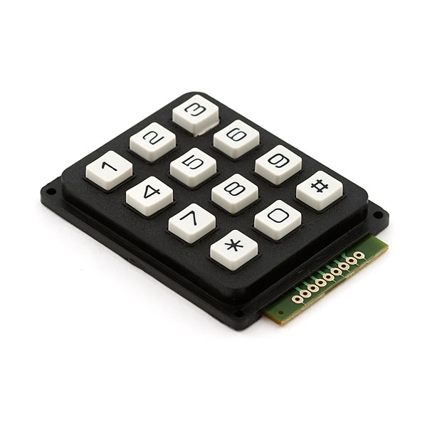
Keypad - 12 Button (COM-08653 ROHS)
This keypad is a basic 12 button pad that is used for user input. These buttons are setup in matrix format which allows the microcontroller to 'scan' the 7 pins to see which of the 12 buttons are being pressed.
Hello World
Import programInput_Keypad
Sparkfun 12 input keypad that hooks up and is built in a 4X3 matrix form.
Library
Import libraryKeyPad
Keypad that has 12 keys for input
Notes

How The Component Works
The keypad pins correspond to either a certain row or certain column then based on which ones are activated then microcontroller can pick out which button was pressed.

Pin Connections
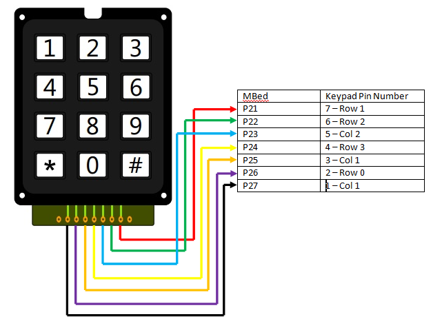
The Keypad is connected through DigitalIn and DigitalOut pins on the microcontroller and for this we used p21-p27. The schematic is built as follows:

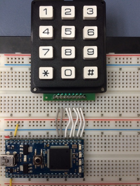
Physical Layout

Video Demo
Datasheet & Sparkfun Order Page
Datasheet: http://dlnmh9ip6v2uc.cloudfront.net/datasheets/Components/General/SparkfunCOM-08653_Datasheet.pdf
Sparkfun: https://www.sparkfun.com/products/8653
Example Code
Example Code for main.cpp
#include "mbed.h"
#include "KeyPad.h"

/*  DigitalOut columnoneout     ( p25 );    // pin 3 on keypad
    DigitalOut columntwoout     ( p27 );    // pin 1 on keypad
    DigitalOut columnthreeout   ( p23 );    // pin 5 on keypad

    DigitalIn rowonein          ( p26 );    // pin 2 on keypad
    DigitalIn rowtwoin          ( p21 );    // pin 7 on keypad
    DigitalIn rowthreein        ( p22 );    // pin 6 on keypad
    DigitalIn rowfourin         ( p24 );    // pin 4 on keypard */

#include <iostream>
int main() {
    Serial pc(USBTX, USBRX); // tx, rx
    KeyPad2 keypad(p25, p27, p23, p26, p21, p22, p24);
    DigitalOut led1(LED1);
    DigitalOut led2(LED2);
    DigitalOut led3(LED3);
    DigitalOut led4(LED4);
    led1 = 0; led2 = 0; led3 = 0; led4= 0;
    pc.printf("starting to print\n");
    while(1) {
        std::vector<int> keys =  keypad.getkey();
        for (int i=0;i<keys.size();i++){
            pc.printf("\nValue:  %d : ",keys[i]);

        }
        wait(.1);
    }
}
You need to log in to post a discussion


