Force Sensing Linear Potentiometer
Force-sensing linear potentiometers (FSLPs) are passive components with resistances that depend on the magnitude and location of the force applied to the strip, making it easy to add novel touch interfaces or tactile sensors.
Hello World

Library
Notes
Force Sensing Linear Potentiometer: 4” x 0.4” Strip

A Force sensing linear potentiometer (FSLP) is a passive component with internal resistances that independently change in response to the magnitude and location of an applied force. This allows a microcontroller to easily determine where and how hard the FSLP is being pressed, enabling advanced touch control users interfaces or sophisticated tactile sensors. Note the FSLP is not a load cell or strain gauge, and it is not suitable for precision force measurements. The FSLP can be purchased at https://www.pololu.com/product/2730.
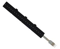
The FSLP is light (1.4g) and extremely thin (0.02”), and it has an active sensing area of 3.9” x 0.37” that can be trimmed to shorter, predefined lengths (1”, 2”, or 3”) to better suit your application. Please refer to the figure 1 below. Note that in order to get the full 4” range of the strip, the three tabs must be cut off. These three tabs determine the active length of the strip, and with all three tabs intact, only the first inch of the sensor will be active. A full instruction on how to customize your FSLP can be found here: https://www.pololu.com/file/0J751/FSLP-10cm-Customization-Guide.pdf

Figure 1. Customizing the length of the 4″ FSLP strip.
Using a FSLP
The FSLP is a three terminal device with two driver lines and one sense line, as shown in figure 2. When pressure is applied, its internal circuit is equivalent to three resistors. Reading the magnitude of the pressure requires an external resistor be added to the circuit, so a total of four microcontroller pins are required. For detailed information, including theory of operation, performance data, circuit diagrams, and usage tips, please refer to here: https://www.pololu.com/file/0J750/FSLP-Integration-Guide-13.pdf. Figure 3 shows a simple circuit diagram used in FSLP_Serial_Output library.

Figure 2. Pinout of the 4.0″×0.4″ force-sensing linear potentiometer (FSLP) strip.

Figure 3. Connection diagram for reading a force-sensing linear potentiometer (FSLP) with a mbed LPC1768.
Measuring pressure
The resistance Rp depends directly on the magnitude of the applied pressure, changing from around 300 kΩ at very light touches to around 1 kΩ when pressing very hard. If the pin connected to D1 is driven high and pin connected to the bottom of resistor Ro is driven low, the SL pin becomes the output of a resistive voltage divider with Rp on top and the external resistor Ro on the bottom. Measuring the voltage at terminal D2 gives the input voltage to this pressure-dependent voltage divider and allows the pressure measurement to be made independent of R1 and R2, which change depending on where the strip is being touched. Once you have measured the voltage divider input (D2 voltage) and output (SL voltage), you have everything you need to compute Rp, which is directly related to the pressure.
The optimal value for Ro depends on the specific application, but a value between 4.7 kΩ and 10 kΩ should work fine for most projects. In this project we use a 10 kΩ resistor.
Measuring position
The strip also functions as a linear potentiometer, with the applied pressure (e.g. your finger) acting as the wiper. As the point of applied pressure moves from one side of the strip to the other, R1 will get smaller and R2 will get bigger, or vice versa (the sum of R1 and R2 is typically around 1 kΩ to 1.5 kΩ per inch of the strip). If the pin connected to D1 is driven high and the pin connected to D2 is driven low, the SL pin becomes the output of this linear potentiometer (the pin connected to the bottom of Ro should be set as a high-impedance input to effectively remove Ro from the circuit). The voltage on the SL pin should range from 0 to Vcc (logic low to logic high) as the pressure application point moves from one extreme to the other.
We use the Window USB serial port to print out the position value and pressure value. For more information on how to use the Window USB serial port, please refer to here https://developer.mbed.org/handbook/Windows-serial-configuration
If you have wired things correctly and run the example code given in FSLP_Serial_Output library, you should be able to see position and force readings in the Window USB serial port like the one shown below:

The video below shows a simple project with a FSLP being used to control RGB LEDs. Codes can be found in FSLP_Controls_RGB_LEDs library. Note that with a lightly touch, position determines the number of red LEDs that light up, and pressure determines the color of the LEDs.
Reference
You need to log in to post a discussion