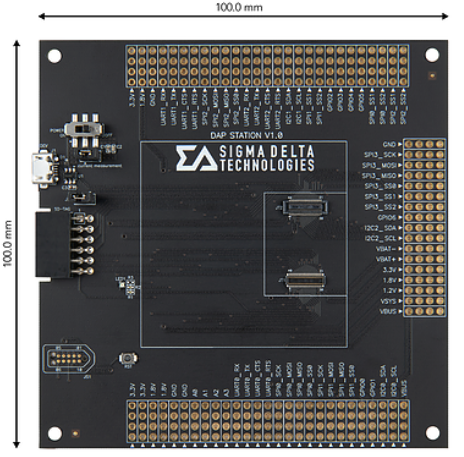
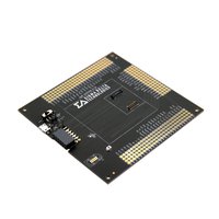
DAP Station Ver.1 | Expansion board for developing SDT Boards
Development and evaluation station for debugging SDT Boards
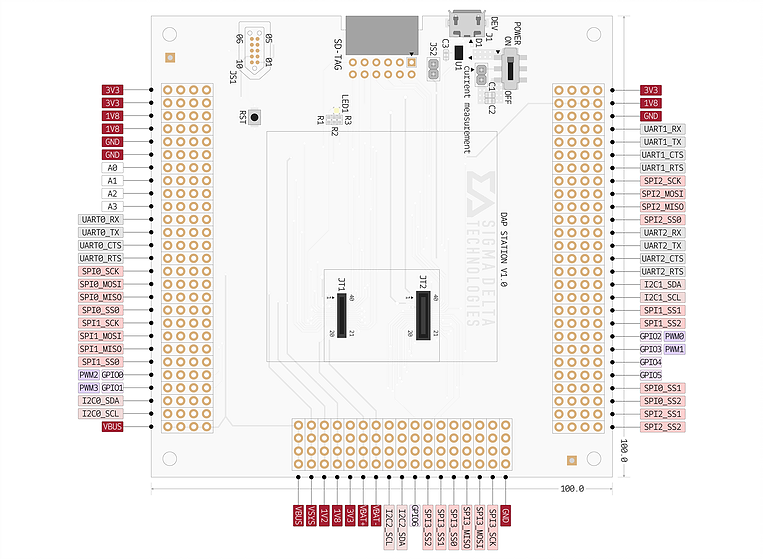
Pinout

Notes

Board Features
- Serial Peripherals
- USB 2.0
- 1 x TC2050
- 1 x SD-TAG
- 3 x UART Interface (12 pins)
- 4 x SPI Interface (24 pins)
- 3 x I²C Interface (6 pins)
- 7 x GPIO
- 4 x Analog
#Sigma Delta Technologies
How to use DAP (Debug Access Port) Station
1. General Description
The DAP Station Ver.1 is a development and evaluation board for debugging the SDT Board.
It provides convenient debugging with easy and intuitive interface. In addition, all pins can be connected
to the exterior, making it very easy to test all pins. The DAP Station Ver.1 cannot be used independently. It
should be connected with SDT Board to measure data values and can be used to debug the SDT Board
by connecting with the Interface.
2. Benefits and Features
- Simple connection
- Micro-USB Type-B connection for SDT Board Power Supply.
- Easy debugging and programming SDT Board via Interface.
- Header Connector with 0.100” (2.54mm) pitch for accessing the General Pins.
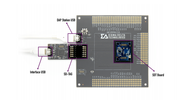
3. How to connect DAP Station Ver.1 with SDT Board and Interface

- Prepare the Interface suitable for the SDT Board.

- Connect SDT Board to DAP Station.
- Use SD-TAG of Interface to connect with DAP Station.

- Connect PC to Interface using Micro B-Type USB.
- Supply power to SDT Board using DAP Station’s Micro B-Type USB Connector.
- Use the online compiler on the Arm Mbed homepage or CLI to program and compile.
- Move the compiled file (.bin or .hex) into the DAPLink drive.
- For efficient connection, the SD-TAG of the DAP Station and the SD-TAG of the
Interface (Table 2) are symmetrically positioned.
- IN11 uses JTAG_TDO pin to serve as SWO.
- IN11 and IN25 support SWD and UART communication for programming and debugging. They
do not support JTAG.
Click the below link to buy DAP Station Ver.1
- Product Link
You need to log in to post a discussion


