ArduIMU
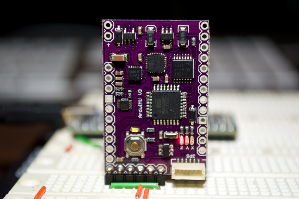
A breadboard friendly IMU focused on Drones / Quadcopters with onboard 3-axis gyro, accel and mag and GPS.
Hello World
Import programArduIMUHelloWorld
Test program testing ArduIMU Library
Library
Import libraryArduIMULib
Library to interface mbed with ArduIMU
Datasheet
http://dlnmh9ip6v2uc.cloudfront.net/datasheets/Robotics/ArduIMU328-v3.pdfNotes
Introduction
The ArduIMU is an IMU specifically designed with other Arduino based auto pilot/quadcopter applications. WIth a little tweaking, we can get it to work with any application! The ArduIMU v3 is a serial device powered by Arduino. The device sports a 3 axis accelerometer, a 3 axis gyroscope, and a 3 axis magnetometer to make it a 9 axis IMU.

Required Hardware
- ArduIMU v3
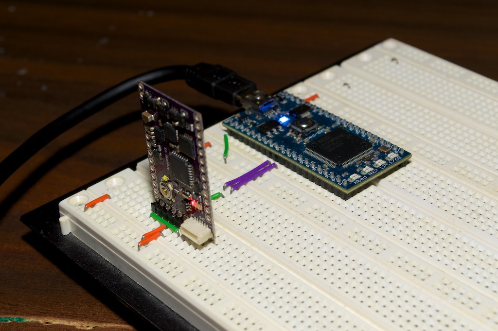
- mbed LPC1768
- FTDI Cable TTL-232r-3v3 (This is required to initially program the Arduino on the ArduIMU, but is not needed specifically to connect it to the mbed.)
- Soldering kit (This is only required once when adding the header pins to the ArduIMU)
Setting up the ArduIMU firmware
Note: This has been written for the ArduIMU v3. As of writing the ArduIMU v4 has not been released.
Upon receiving the IMU, a couple things must be done including soldering the header pins. The IMU wiki has detailed instructions: ArduIMU Wiki
If you chose to use the latest firmware. (1.9.7) there is a bug with the Arduino API that makes binary output mode output ASCII by mistake. You have to replace every instance in Output.ino of Serial.print with Serial.write when binary mode is expected. I have attached a correct Output.ino file which is a copy from the google code issues page. Output.ino
After verifying the ArduIMU works with a PC and the FTDI cable, you can now flash the ArduIMU for use with the mbed library. The mbed is expecting the following values to be set in the Arduino code. The main thing you want to ensure is that PRINT_BINARY is set to 1. Other values might only affect performance, or have no effect at all.
#define PRINT_DEBUG 0
#define PRINT_DCM 0
#define PRINT_ANALOGS 0
#define PRINT_EULER 1
#define PRINT_GPS 0
#define PRINT_MAGNETOMETER 0
#define PRINT_BINARY 1 //The most important value.
Connecting the ArduIMU to the mbed
| mbed | ArduIMU |
|---|---|
| VU | 5V |
| GND | GND |
| p10 | TX |
| p9 | RX |
The p9 to RX pin is unused in the current version of the ArduIMU code, however it is very easy to add code to respond to commands send over serial. This is not within the scope of this document.

Some people have reported problems with UART devices unless they short the CTS and RTS lines. In the pictures above you can see this is shorted. I had no problems either way.
Possible improvements/Known bugs
This code only works when there is no GPS module attached. If there is not GPS module, there will be considerable "Yaw Drift" which means the yaw reading is fairly unreliable in the long run.
You need to log in to post a discussion


