Tutorial on debugging I2C with numerical scope
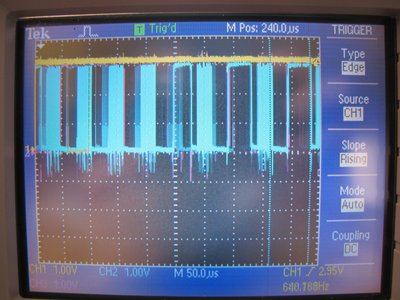
This is a first version on a tutorial describing with details how to debug I2C master/slave exchange (refer to http://en.wikipedia.org/wiki/I%C2%B2C for I2C protocol description) using a numerical scope (Tektronix TDS2014 4 channels 100MHz here).
1. Software configuration
- Use a GPIO to trigger the beginning of the I2C read/write operation setting the GPIO hight level when entering in read/write function and setting the GPIO to low level leaving it
- The I2C operation to debug (read or write) is placed into an infinite loop:
        while(1) { // Use infinite loop to test one of both function using num. scope
            m24LCxx_writeBytes(10, message, strlen(message), 0);
            //m24LCxx_readBytes(10, rx, 0, strlen(message));
        }
2. Probes assignment
- CH1: On GPIO trigger (Yellow signal)
- CH2: On SCL line (blue signal)
- CH3: On SDA line (pink signal)
- CH4: switched off

3. Scope settings
- All channels are set on 1V/div in 3.3V power supply or 2V/div in 5V power supply
- Time base is set on 50 us/div
- The horizontal trigger threshold level is set on the left position
- Triggering is set on CH1, in sample mode, on rising edge, level is set to 50%
4. Signal acquisition
- Launch the application in debug mode
- Captured signals shall be displayed by the scope
- Press on Single Seq to capture one I2C frame
- Reduce the time base around 5us/dev to visualize different part of the I2C frame:
- For a I2C write:
- External trigger is set to logical level 1 (Yellow signal)
- Start bit
- Device address + slave ACK
- Memory address + slave ACK
- Data + slave ACK
- Stop bit
- External trigger is set to logical level 0 (Yellow signal)
- For a I2C write:
- External trigger is set to logical level 1 (Yellow signal)
- Start bit
- Device address + slave ACK
- Memory address + slave ACK
- Data + slave ACK
- Stop bit
- External trigger is set to logical level 0 (Yellow signal)
5. Frame analyzing
- Activate Cursor functionality on CH2 (SCL line/blue signal)
- Place the cursor to each SCL high level and read the SDA value (pink signal)
- Compare capture timing diagram with expected timing diagram from I2C IC datasheet
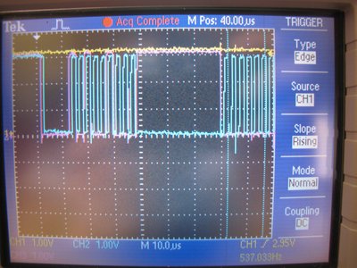
The screenshot below shows the first part of the I2C frame with the I2C Start bit and the device address. The MSB part of the device address is the Microchip identifier (0xA),

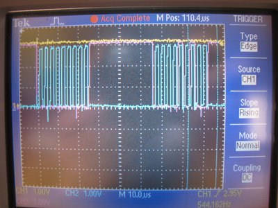
This screenshot shows the second part of the I2C frame with the memory address on two byte. The MSB address part is 0x00 and the LSB part is 0x0A (memory address #10).

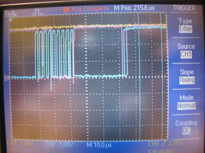
This screenshot shows the last and not the least part of the I2C frame with the data value to store in memory address #10 and the I2C Stop bit.

5 comments on Tutorial on debugging I2C with numerical scope:
Please log in to post comments.

Hi Yann, this looks useful to me, but I don't understand the code. Is it possible to just keep sending an I2C command from the mbed in an infinite loop without the need for an ack? Thanks