Important changes to forums and questions
All forums and questions are now archived. To start a new conversation or read the latest updates go to forums.mbed.com.
12 years, 6 months ago.
mbed LPC1768 clock out to clock in pin on pump
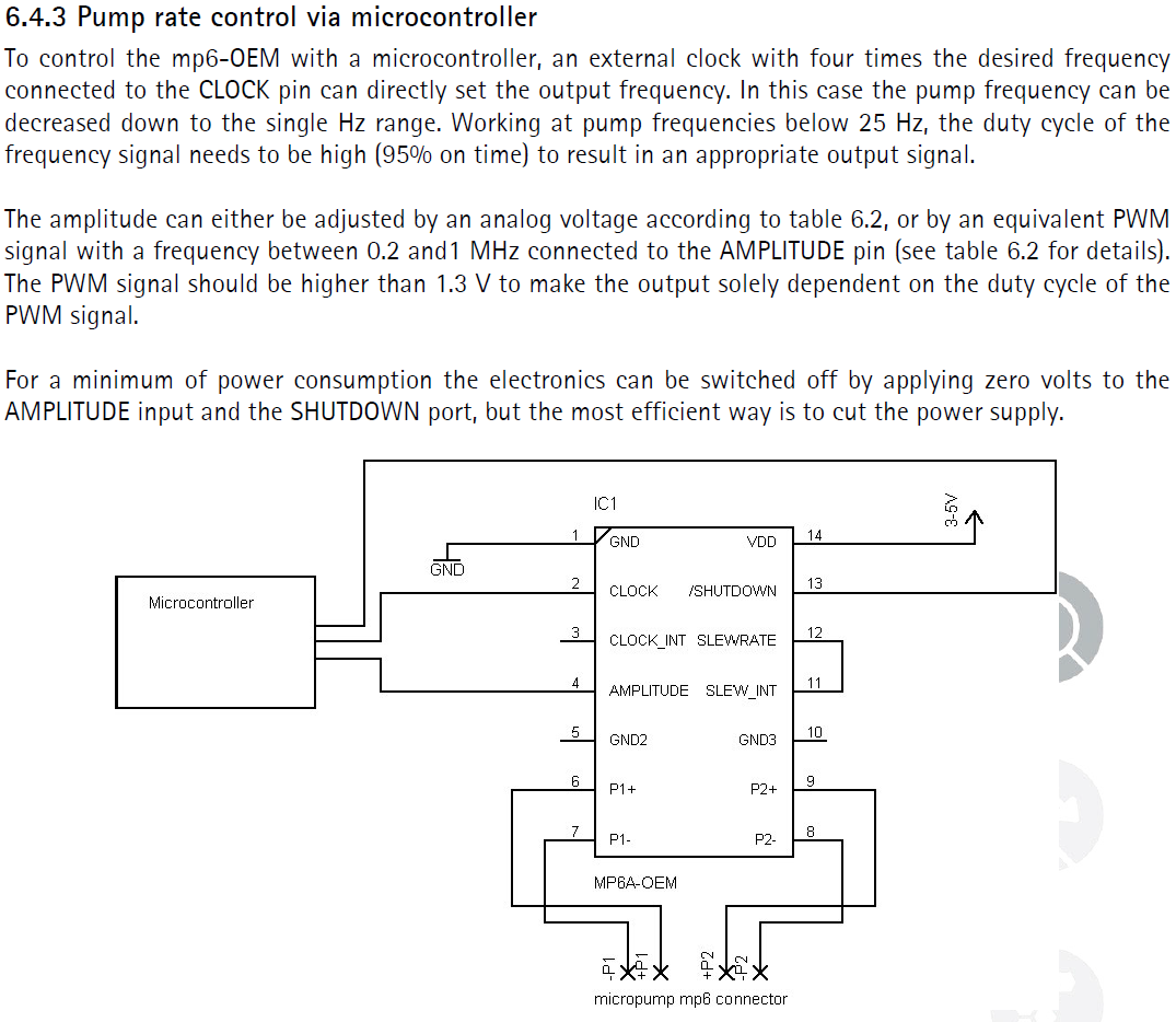
I was wondering if someone could help me use the mbed LPC1768 as per the attached schematic. I am unsure about connecting the clock from the microcontroller to the OEM board as I am no expert in this stuff.
My purpose is to test a pump I have using the microcontroller.
Many Thanks

2 Answers
12 years, 6 months ago.
The description is not very clear. A full datasheet would be needed for better advice. The clock frequency is not clear. You can probably use a regular DigitalOut pin and a Ticker to toggle it a the desired rate if it is not too high. Obviously, you can also use a PWM output. That may be easier and takes no processing time away from the mbed. The amplitude input is even less clear. Table 6.2 should give info on the required voltages. You can use the AnalogOut pin of mbed for that purpose or use another one of the PWM outputs as long as the frequencies dont conflict (all PWM outputs have the same frequency).
12 years, 6 months ago.
Thanks for your speed answer...
The clock frequency is to be 4 times the desired frequency of the pump (Piezo pump), therefore since I am testing this pump for a particular fluid, I need to vary this frequency from 80Hz - 400Hz to find the desired frequency for a particular flow rate at a constant temperature.
Would you recommend using a digital signal or analogue for the clock? Also, would it matter the amplitude of the clock signal?
Many thanks
The clock freq should be 4x the desired freq for the pump. So it should be between 320Hz (4x80Hz) and 1600Hz (4x400Hz). I would use a PWM output for those frequencies. See http://mbed.org/handbook/PwmOut
Set the dutycycle for the PWM pump pin at 50% using pump.write(0.5) and select the frequency as desired by calling pump.period_ms() with period times that match the freq range 320Hz to 1600Hz. The outputvoltage will be either 0V or 3V3. That should match the mp6-OEM input.
The other input of the mp6-OEM that needs to be controlled is the Amplitude pin. You should use the mbed AnalogOut pin to drive that input. I dont see what the valid range is for the mp6. The mbed analog output can provide any voltage between 0V and 3V3. The PWM outputs are not suitable for this purpose since the freq is now always between 320Hz and 1600Hz while the mp6-OEM seems to need at least 0.2MHz
posted by 19 Jul 2013