Important changes to forums and questions
All forums and questions are now archived. To start a new conversation or read the latest updates go to forums.mbed.com.
12 years, 7 months ago.
Pin connection on LPC1768 if using FTDI cable
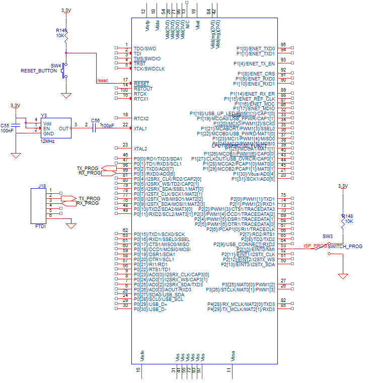
I am presently working on a projet using the LPC1768. I'm making my PCB and I was doing some last minut verifications when a question poped up. I am using a FTDI TTL-232R-3V3 (http://www.digikey.com/product-detail/en/TTL-232R-3V3-2MM/768-1095-ND/2507857) cable to program my LPC1768 and i was wondering if i needed to do anything with the JTAG pins (pull-up or pull-down) or if i could simply leave them floating. I used this (http://mbed.org/media/uploads/chris/lpc1768-refdesign-schematic.pdf) schématic as reference. Am i right to think that if i am using ISP programming i don't need to care about the JTAG pins?
this is what i have right now

Thanks for your time
Julien Duchesne
3 Answers
12 years, 7 months ago.
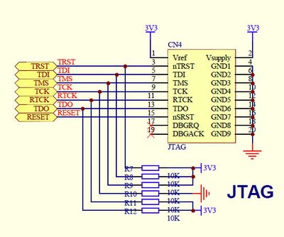
It will be safer to use some pull-up or pull-down resistors on the JTAG pins even if you dont plan to use them. The reference schematic is a good wiring example. Here is another one:

12 years, 7 months ago.
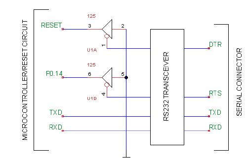
If you connect:
DTR to Reset
RTS to ISP
with a 1 - 5 K resistor, then Flash Magic can fully program the LPC1768 using this circuit:

(from Flash Magic documentation.)
or two small transistors, with appropriate resistors.
in Open Collector mode.
Hope that helps.
Ceri
12 years, 7 months ago.
Thank you Ceri! =)
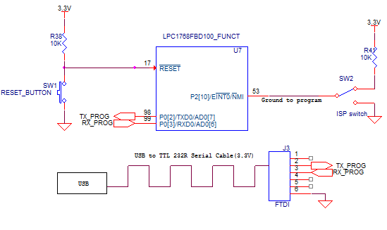
But... i think that justed mixed me up un bit more because i am using a câble that already has a RS232 transceiver. I read this page (http://mbed.org/users/chris/notebook/prototype-to-hardware/) and read almost all the comments and i can up with this 
Could you tell if this will work? I am almost certain but would only like a confirmation! The usb to TTL 232 serial cable is this one (http://www.digikey.com/product-detail/en/TTL-232R-3V3-2MM/768-1095-ND/2507857).
Thanks for your time =)
Julien
Yes it will work, But be warned, the VCC from the FTDI cable is 5 Volts
This will KILL LPC1768 chip !!!!
I only suggested the above circuit, because it is not always possible to press switches & program,
or am i lazy
Ceri, you are correct that a classic FTDI cable with 5V Vcc will kill the LPC1768 unless you use a voltage regulator like the 1117-3V3. The regulator would be a good idea anyhow because you can then also use USB as powersupply.
The circuit that you propose for automated activation of the ISP bootmode should work fine. The problem with the standard FTDI cable is that it does not provide the DTR pin. You only get RTS and CTS.
I have modified a cheap (actually I got it for free...) mobilephone datacable which uses the PL2303 to provide both 3V3 power and RTS/DTR. It may be possible to adapt an FTDI cable/circuit in the same way depending on your hardware.
posted by 18 Jul 2013