ST7735 SPI 1.8" TFT + mbed (work in progress)
The Library and demo
- http://mbed.org/users/smultron1977/libraries/ST7735_TFT/m20nw8
- http://mbed.org/users/smultron1977/programs/SPI18TFT/m2165x
Background
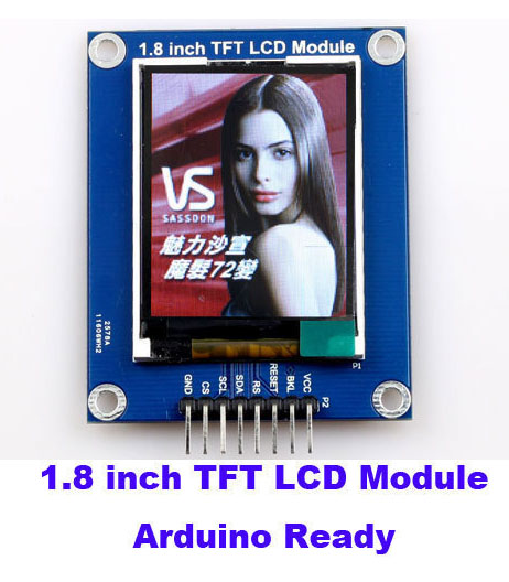
I bought a cheap 1.8" TFT breakout for 15USD from ebay. The breakout has a 128x160 TFT, a ST7735 graphics controller, SD card cage and 10-pin interface with SPI. This notebook entry is about finding the pinout & writing a library for mbed.
The library is working, but still has some bugs I want to get rid off before publishing. The library was written by combining info from ST7735 datasheet, Ladyada's Adafruit ST7735 lib for Arduino and Peter Drescher's SPI for QVGA TFT library for mbed http://mbed.org/users/dreschpe/notebook/qvga-tft-with-hx8347d-controller/?c=2222
Many thanks to Peter for his work on the QVGA TFT.
The breakout


http://www.ebay.com/itm/ws/eBayISAPI.dll?ViewItem&item=280751182006&ssPageName=ADME:L:OC:US:1123
Pinout
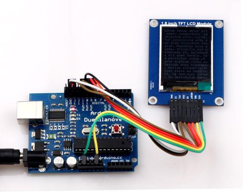
TFT -> MBED
- P1 GND -> GND
- P2 SD-CS -> NC
- P3 LCD-CS -> P8
- P4 SCLK -> P7
- P5 MOSI -> P5
- P6 MISO -> P6
- P7 RS -> P11 (ST7735 needs this to toggle between data & commands)
- P8 RESET -> P15
- P9 BKL -> GND
- P10 VCC -> VU
Progress 30.11. Starfield running
The library has still some bugs that need to be fixed before publishing.
Progress 29.11. Success: pixel on screen
I found the bug. The matter was a simple one: I forgot to write the high 8 bits of the pixel. This was due to me thinking that spi.format was in (16,3) mode, when it was in fact in (8,3) = only 8 bits were written = write operation in the ST7735 was never completed.
You can see my mistake below: only 8 bits after RAMWRITE (0x2C) in the end (compare with the arduino above)

Progress 29.11. ... SPyIng a Pixel in the Nude
After failing to get a pixel on screen by brute force, I decided to do something more elegant. I hooked up my lovely USBeeAX logic analyzer to Arduino nano and the TFT screen and looked at exactly what the Adafruit library on the nano is doing with the SPI bus to send a pixel on screen.
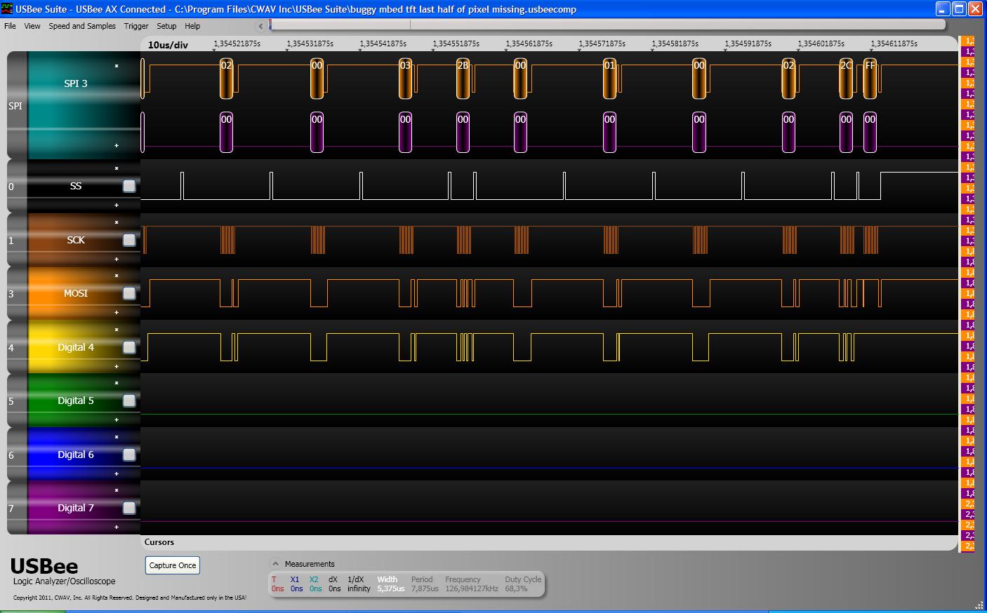
So, below you can see what putting one pixel on screen (black pixel at 1,1) looks like in the nude ! Beautiful isn't it !
0x2A is a command to set column start and end adress, which for some reason is not 1 and 2 but 0x03 and 0x04 ! Useful bit of information !
0x2B is a command to set row start and end, again its 2 and 3 instead of 1 and 2... this will help me alot.
0x2C is the RAM WRITE command that sends the pixel (00 00) to the memory
In this picture you can really see for your self how SPI works:
- SS (sometimes called CS) is pulled low to activate the SPI slave
- SCK (the clock signal) is wriggling up and down to carry data, in this case data is read on the low-to-high edge of the pulse
- MOSI is blinking the bits, that are the actual data
(Ignore the MISO FF's, theyre just hanging around not doing anything)
![]()
Progress 26.11. Init functions working
I now have garbage on the screen + screen is responding to power control / display commands. But graphics functions are not working, need to crosscheck the ST7735 and HX8347, they seem to be different in this respect.
9 comments on ST7735 SPI 1.8" TFT + mbed (work in progress):
Please log in to post comments.

Peter Drescher's SPI for QVGA TFT is here: http://mbed.org/users/dreschpe/notebook/qvga-tft-with-hx8347d-controller/?c=2222