You are viewing an older revision! See the latest version
Pulsno širinska modulacija
Sve vježbe iz ove teme mogu se napraviti pomoću mbed application board-a. Na mbed-u se u svrhu pulsno-širinske modulacije (PWM) koriste pinovi p21 do p26 i klasa PwmOut. Na mbed application board-u pinovi p21 i p22 su spojeni na konektore servo motora, pinovi p23, p24 i p25 su spojeni na RGB LED-icu, a p26 je spojen na piezzo zvučnik.
Generiranje PWM signala
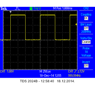
Korištenjem mbed-a kreirajte PWM signal frekvencije 1 kHz i faktora upravljanja (duty cycle) 50%. Snimite signal osciloskopom i provjerite da li je uspješno generiran.
Moguće rješenje dano je u sljedećem programskom kôdu:
Import programMAB_PWM_Oscilloscope_1
A simple 1 kHz PWM signal generator with 50% duty cycle.
Uzorak oscilograma prikazan je na sljedećoj slici:

Modificirajte program tako da se faktor upravljanja (duty cycle) može namještati pomoću potenciometra Pot1 ili utipkavanjem putem terminala.
Rješenje s potenciometrom dano je u sljedećem programskom kôdu:
Import programMAB_PWM_Oscilloscope_2
A simple 1 kHz PWM signal generator with adjustable duty cycle over potentiometer.
Pokrenite program i promatrajte kako se mijenja faktor upravljanja promjenom zakreta potenciometra ili utpkavanjem vrijednosti s terminala.
Upravljanje svjetlinom LED-ice pomoću PWM izlaza
Create a program that controls a brightness of mbed onboard LED1 using PWM. The brightness must be set by using potentiometer Pot2.
The solution is given in the program below.
Import programMAB_PWM_LED1
A simple program that controls the LED1 brightness by using potentiometer.
Exercise 3: Controlling RGB LED color with PWM
A RGB LED consists basically of 3 separate LEDs (red, green and blue). If you take a look at the schematics on the sheet 2, section B1 and B2, you will notice that all 3 LEDs are connected in common anode mode. Therefore, the outputs should be configured as open drain!. Since this is not possible in the PwmOut class, the power supply to the common anode of the LEDs must be 3.3 V (which it is!) for everything to work fine. SInce this basically is the open drain configuration, the logic will be inverse, meaning that 100% duty cycle will turn off the LED, and 0% duty cycle will turn on the LED with full brightness.
Create the program that sets the red color by Pot1, the green color by Pot2 and blue color by pressing the center joystick key (p14).
The solution is given in the program below.
Import programMAB_PWM_RGB_LED
A simple program to control the color of RGB LED.
Exercise 4: Outputting to a speaker
Write a program that will play a Ciciban song on a speaker. The song beat must be adjustable over potentiometer Pot1, and song scales must be adjustable over potentiometer Pot2.
The solution is given in a program below. Enjoy :)
Import programMAB_PWM_Speaker
A program for playing Ciciban song. All notes are included, so any song can be easily added if you know its notes.
Exercise 5: Control of servo motor position
Write the program that will control the position of servo motor via a potentiometer setting. Set the PWM period to 20 ms, 1.5 ms pulse width for reference position (0 degrees), 0.5 ms pulse width for the most left position and 2.5 ms for the most right servo motor position. The values between the most left and right positions must be linearly scaled.
Congratulations!
You have completed all the exercises in the Pulse width modulation topic.
Return to TVZ Mechatronics Team Homepage.

