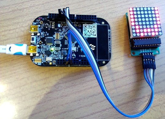
Simple demo to drive a 8x8-as LED matrix by a MAX7219 LED driver IC. After initialisation two characters (H and W) are displayed alternatively. The MAX7219 IC is driven by hardware SPI: SPI0 module at PTD1, PTD2, PTD3.
Dependencies: mbed
SPI MAX7219 demo
Simple demo to drive a 8x8-as LED matrix by a MAX7219 LED driver IC. After initialisation two characters (H and W) are displayed alternatively. The MAX7219 IC is driven by hardware SPI: SPI0 module at PTD1, PTD2, PTD3 (Arduino compatible pins).
Hardware requirements:
- FRDM-KL25Z board
- LED 8x8 matrix with MAX7219 controller
Wiring:
| MAX7219 | FRDM-KL25z | Note |
|---|---|---|
| VCC | 3V3 | Power |
| GND | GND | Ground |
| DIN | D11 | MOSI (PTD2) |
| CS | D10 | Chip select (PTD0) |
| CLK | D13 | SCLK (PTD1) |

Revision 0:bd34a367f642, committed 2015-11-24
- Comitter:
- icserny
- Date:
- Tue Nov 24 06:41:43 2015 +0000
- Commit message:
- First version
Changed in this revision
| main.cpp | Show annotated file Show diff for this revision Revisions of this file |
| mbed.bld | Show annotated file Show diff for this revision Revisions of this file |
diff -r 000000000000 -r bd34a367f642 main.cpp
--- /dev/null	Thu Jan 01 00:00:00 1970 +0000
+++ b/main.cpp	Tue Nov 24 06:41:43 2015 +0000
@@ -0,0 +1,70 @@
+/* 06_spi_max7219_led8x8
+ *
+ * Simple demo to drive a 8x8-as LED matrix by a MAX7219 LED driver IC
+ * After initialisation two characters (H and W) are displayed alternatively.
+ * The MAX7219 IC is driven by hardware SPI: SPI0 module at PTD1, PTD2, PTD3.
+ */
+
+#include "mbed.h"
+
+SPI spi(PTD2, PTD3, PTD1);          // Arduino compatible MOSI, MISO, SCLK
+DigitalOut cs(PTD0);                // Chip select
+
+const unsigned char led1[]= {
+    0xFF,0x18,0x18,0x18,0x18,0x18,0x18,0xFF
+};  //H
+const unsigned char led2[]= {
+    0x1F,0x60,0x80,0x40,0x40,0x80,0x60,0x1F
+};  //W
+
+/// Send two bytes to SPI bus
+void SPI_Write2(unsigned char MSB, unsigned char LSB)
+{
+    cs = 0;                         // Set CS Low
+    spi.write(MSB);                 // Send two bytes
+    spi.write(LSB);
+    cs = 1;                         // Set CS High
+}
+
+/// MAX7219 initialisation
+void Init_MAX7219(void)
+{
+    SPI_Write2(0x09, 0x00);         // Decoding off
+    SPI_Write2(0x0A, 0x08);         // Brightness to intermediate
+    SPI_Write2(0x0B, 0x07);         // Scan limit = 7
+    SPI_Write2(0x0C, 0x01);         // Normal operation mode
+    SPI_Write2(0x0F, 0x0F);         // Enable display test
+    wait_ms(500);                   // 500 ms delay
+    SPI_Write2(0x01, 0x00);         // Clear row 0.
+    SPI_Write2(0x02, 0x00);         // Clear row 1.
+    SPI_Write2(0x03, 0x00);         // Clear row 2.
+    SPI_Write2(0x04, 0x00);         // Clear row 3.
+    SPI_Write2(0x05, 0x00);         // Clear row 4.
+    SPI_Write2(0x06, 0x00);         // Clear row 5.
+    SPI_Write2(0x07, 0x00);         // Clear row 6.
+    SPI_Write2(0x08, 0x00);         // Clear row 7.
+    SPI_Write2(0x0F, 0x00);         // Disable display test
+    wait_ms(500);                   // 500 ms delay
+}
+
+int main()
+{
+    cs = 1;                         // CS initially High
+    spi.format(8,0);                // 8-bit format, mode 0,0
+    spi.frequency(1000000);         // SCLK = 1 MHz
+    Init_MAX7219();                 // Initialize the LED controller
+    while (1) {
+        for(int i=1; i<9; i++)      // Write first character (8 rows)
+            SPI_Write2(i,led1[i-1]);
+        wait(1);                    // 1 sec delay
+        for(int i=1; i<9; i++)      // Write second character
+            SPI_Write2(i,led2[i-1]);
+        wait(1);                    // 1 sec delay
+    }
+}
+
+
+
+
+
+
diff -r 000000000000 -r bd34a367f642 mbed.bld
--- /dev/null	Thu Jan 01 00:00:00 1970 +0000
+++ b/mbed.bld	Tue Nov 24 06:41:43 2015 +0000
@@ -0,0 +1,1 @@
+http://mbed.org/users/mbed_official/code/mbed/builds/9296ab0bfc11
\ No newline at end of file
 hobbielektronika