Important changes to forums and questions
All forums and questions are now archived. To start a new conversation or read the latest updates go to forums.mbed.com.
6 years, 6 months ago.
NXP LPC1768 board use P0_28 and P0_27 as I2c pins.
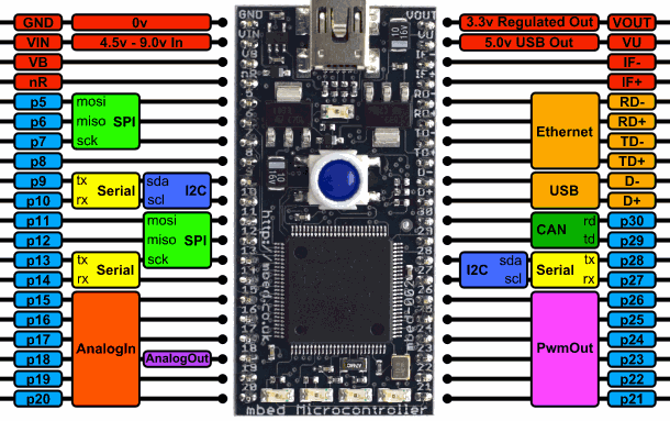
I have been working on an application using I2C on the NXP LPC1768 board. However I found that the default I2C pins as seen on this diagram: https://os.mbed.com/media/platforms/lpc1768_pinout.png don't appear to be able to pull down below 0.7V or so. (I tried several values of pull ups). Pulling up the chip datasheet: https://www.nxp.com/docs/en/data-sheet/LPC1769_68_67_66_65_64_63.pdf I noticed that the assigned i2c pins on the board don't seem to actually be proper open drain outputs! e.g. "SDA1 — I2C1 data input/output. (This is not an I2C-bus compliant open-drain pin)."
The chip however does seem to have actual proper open drain I2C outputs, P0_28 and P0_27. I tried to get mbed to use these instead of the "normal" pins but could not get this working. Is it possible to use these pins? And if so, what do I have to do to accomplish this?
Any help appreciated!
1 Answer
6 years, 6 months ago.
Hi Jeroen,
You can initialize the I2C pins by I2C i2c(I2C_SDA2 , I2C_SCL2); , that would assign P27 as I2C SCL, P28 as I2C SDA.
The APIs of I2C can be referred here.
https://os.mbed.com/docs/mbed-os/v5.14/apis/i2c.html
Regards, Desmond