Important changes to forums and questions
All forums and questions are now archived. To start a new conversation or read the latest updates go to forums.mbed.com.
8 years, 9 months ago.
Default delay between PWM1, PWM2, and PWM3 channels
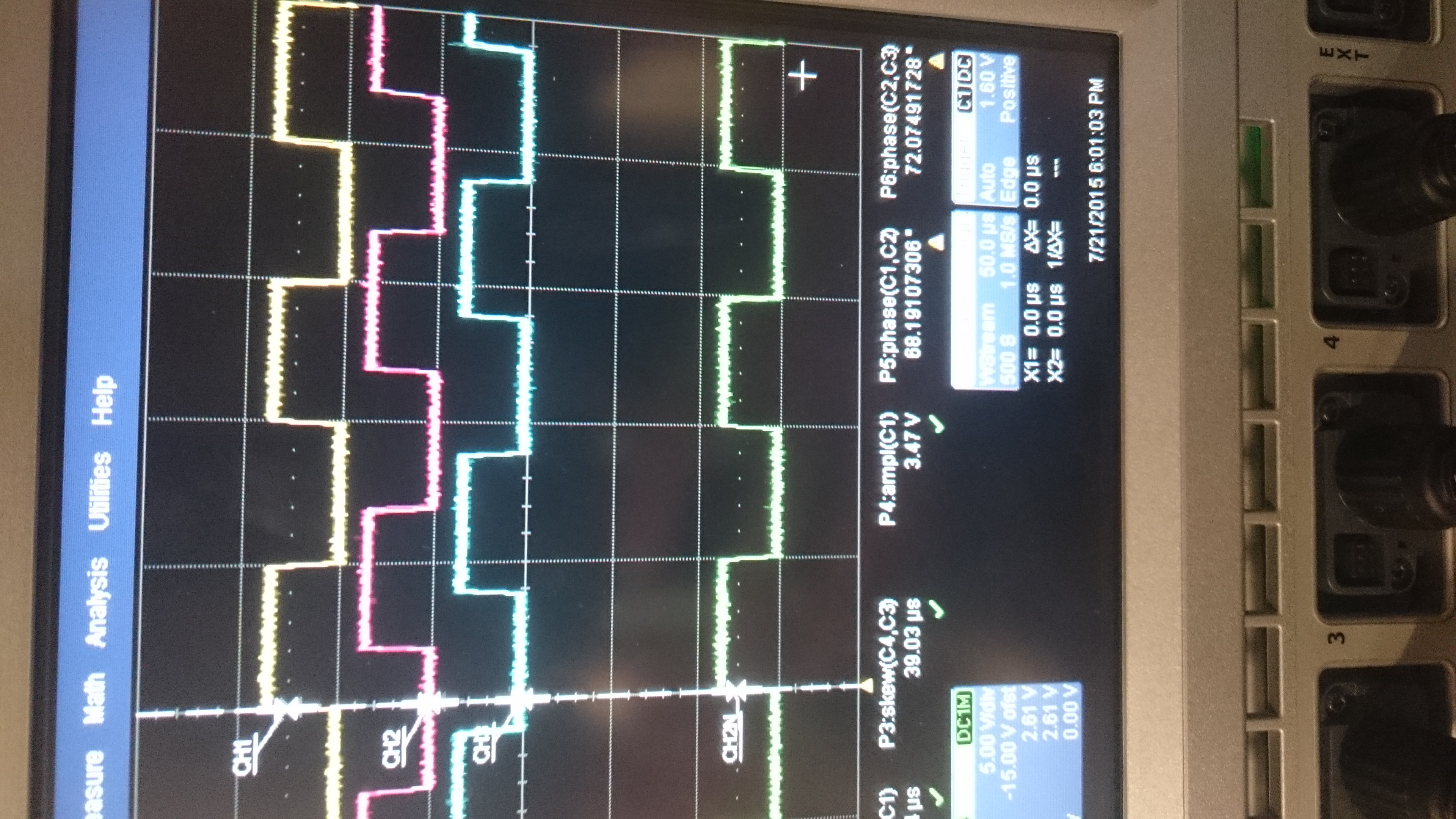
I have generated 3 PWM signals each using individual timers PWM1/1, PWM2/1, PWM3/1
The results on the oscilloscope were as follows:

Is there a way to adjust the default delay between the channels from the 70 degrees that it currently is to 120 degrees?
Thank you in advance
1 Answer
8 years, 9 months ago.
The info on the behaviour of PWM and pinnaming convention is here https://developer.mbed.org/teams/ST/wiki/pinout_labels
Use 3 pins with the same timer to generate 3 outputs with the same frequency. Use a lookup table to vary the duty cycle of a PWM to generate a sinewave. A timer is used to update the index into the table at regular intervals. You can generate three PWMs with a specific phase relation by adding different offsets (modulo max index) to the counter index.
An example for one channel sine from PWM is here: https://developer.mbed.org/users/wim/notebook/pwm-to-generate-analog-waveforms-/
You will have to dive into the documentation and modify the mbed library code in case you want to use synchronised PWMs with different timers. Have not checked, it may not be possible. The standard lib also does not support non-overlapping PWMs, which is probably what you want instead of just complementary outputs. I am assuming you want to drive some output FETs for motorcontrol applications.
Wim
Thank you for your response. You are correct. I wish to drive a three phase motor using a PWM inverter that requires 6 PWM signals, three shifted 120 degrees and their complementary signals. Also dead time of 4us is required.
Thank you for the example. I have created a similar program that calculated values of a sine function and splits them up in 100 points, these points are then written to the duty cycle of the pwm signals.
Code as follows if you are interested:
- include "mbed.h"
- ifndef M_PI
- define M_PI 3.14159265358979323846
- endif
DigitalOut myled(LED1); PwmOut CH1(PA_8); PwmOut CH2(PA_15); PwmOut CH3(PA_6);
- Ticker interrupt; InterruptIn button(USER_BUTTON);
int n; double dc_min = 0.0, dc_max = 1.0;
void sine_dc() { double dc, sine_term;
n = n + 1; if(n == 100) n = 0; sine_term = (1 + sin(2*M_PI*n/100.0)); dc = sine_term * dc_min + (2 - sine_term) * dc_max; CH1.write(dc/2); CH2.write(dc/2); CH3.write(dc/2); }
int main() { int f = 20000; n = 0; CH1.period_us(100); CH1.write(0.5); CH2.period_us(100); CH2.write(0.5); CH3.period_us(100); CH3.write(0.5);
interrupt.attach_us(&sine_dc, f);
while(1) { myled = !myled; wait(1); } }
At the moment I am using PWM1/1, PWM2/1 and PWM3/1, but the pin-outs can be changed to use PWM1/1, PWM1/2, PWM1/3 easily.
I have also read that it is not possible to use PWM1/1 and PWM1/1/N at the same time, is this true?
Thank you again for your response, I will report back if I make any breakthroughs.
Christiaan
posted by 22 Jul 2015