Important changes to forums and questions
All forums and questions are now archived. To start a new conversation or read the latest updates go to forums.mbed.com.
9 years, 7 months ago.
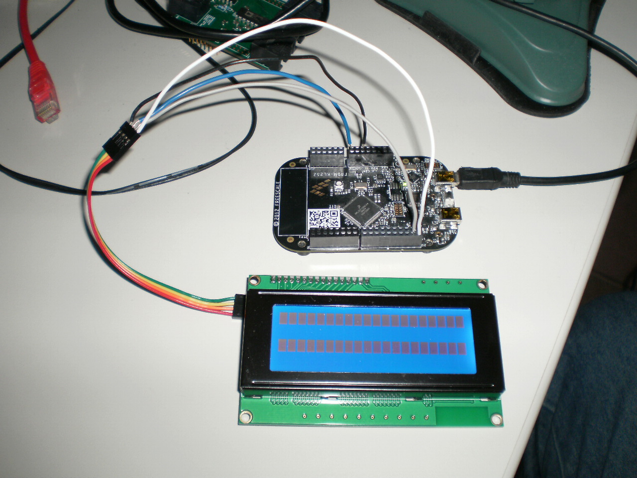
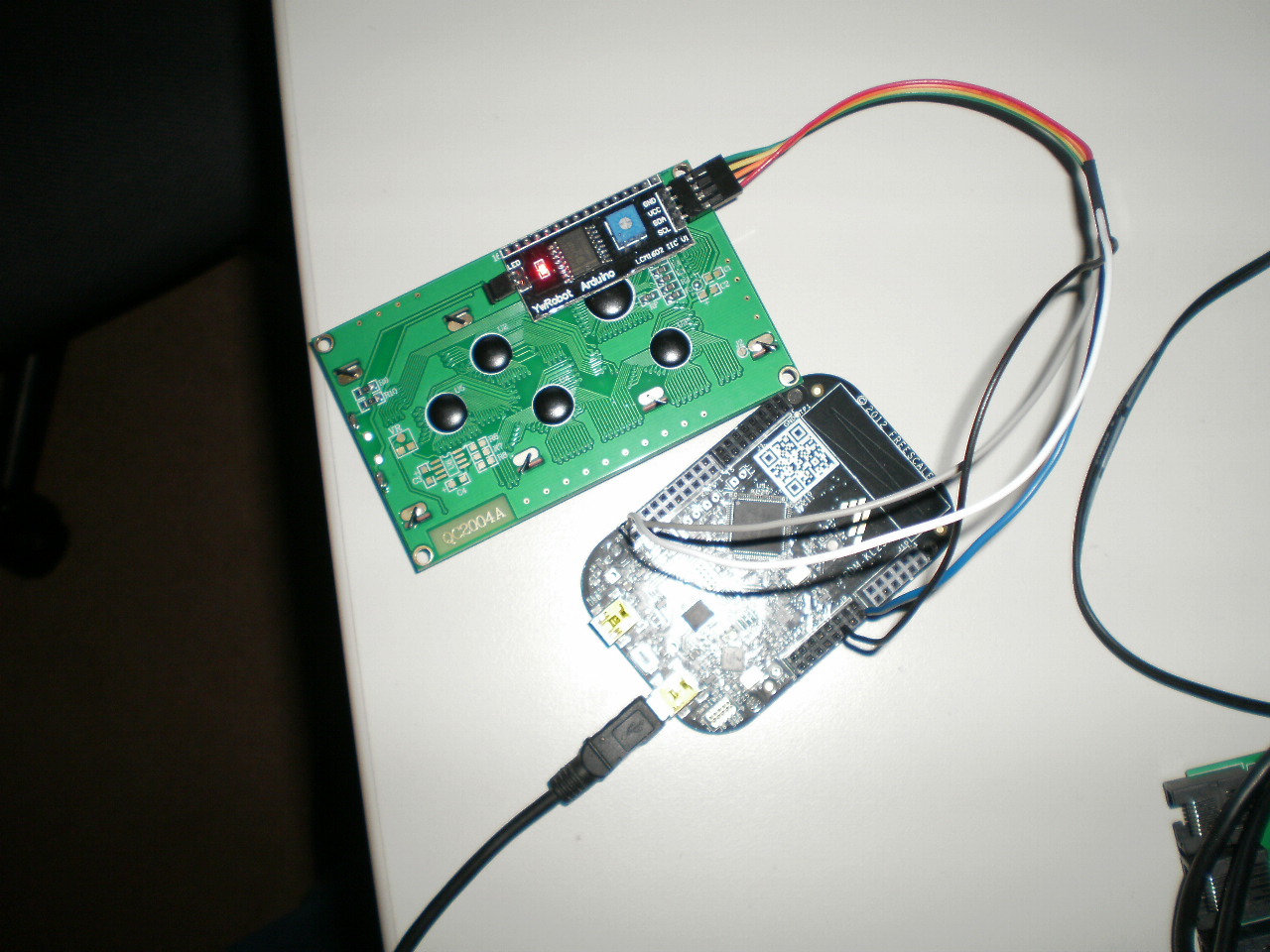
LCD 20x4, YwRobot Arduino LCM1602 IIC V1, I2C will not work
Good day,
Can some body give me a hand.
If have got a Blue LCD 20x4 character, I2C connected to a KL25Z. (Gnd/5V/SDA/SCL == GND/5V/PTE0/PTE1) The LCD is marked YwRobot Arduino LCM1602 IIC V1


<</code>>
- include "mbed.h"
- include "TextLCD.h"
YwRobot Arduino LCM1602 IIC V1 Philips PCF8574T adres = 0x4E Set as DFROBOT 1 20x4 characters
Host PC Communication channels Serial pc(USBTX, USBRX); tx, rx
I2C Communication I2C i2c_lcd(PTE0,PTE1); SDA, SCL
TextLCD_I2C lcd(&i2c_lcd, 0x3F, TextLCD::LCD20x4);
int main() {
while(1) { pc.printf("print "); lcd.setAddress(0,0); lcd.printf("Hello World_1"); wait(0.5); } } <</code>>
Question relating to:
1 Answer
9 years, 7 months ago.
Hi Gerrit You say the address should be 0x4E since the A0-2 are all 1. However, your code shows 0x3F as slave addresss in the declaration of the LCD, so you should change that. Also note that to select the DFROBOT pinout you must set the correct define in the TextLCD_config.h file. Make sure that you have pull-up resistors on the SDA and SCL lines. I am not sure that your PCF8574 interface module has these on the board.
Regards, Wim
Dear Wim,
Very sharp, you are right the pull-up resister are missing....will be soldering on sunday.
Many thanks, Gerrit
posted by 04 Oct 2014Wim, Works like a charm with two 4k7 pull-up resisters on between Vcc(5v)-SCL and Vcc-SDA. Address was 0x4E, LCD4x20, DFROBOT 1, Backlight switched on, revere logic with lcd.setBacklight(TextLCD::LightOff); LCD model HD44780U, Expander PCF8574 (YwRobot Arduino LCM1602 IIC V1). Thanks, Gerrit
posted by 05 Oct 2014Good to hear that it works. I will have a look at the Backlight. There are quite a lot of very similar, yet (slightly) different I2C expander clones for LCDs. Some have hardcoded addresses, others have jumpers or solderbridges. Some support backlightcontrol through a programmable bit (positive or inverted logic) and some just use a jumper for on/off. Some have pull-up resistors, others dont. I will probably add a separate option for the YwRobot module in the next release of TextLCD lib.
posted by 05 Oct 2014
Oops something went wrong i was not yet finished with the question.
The question is does somebody recognize this LCD display. I have measured PCF8574 pins A0,A1,A2 all high the Address byte value must be 0x4E (0x27 7-bit without R/W.)
The display is discribed at http://www.datsi.fi.upm.es/docencia/Informatica_Industrial/DMC/LCD-Blue-I2C.htm. See also http://www.extremeelectronics.co.uk/blog/i2c-control-of-lcd-display-using-ywrobot-lcm1602-v2-raspberry-pi/
I think the hardware connection are as in DFROBOT 1
Any idea's ?
Thanks
Gerrit
posted by Gerrit Pathuis 04 Oct 2014Wim, I want to thank you for all the hard work on this and taking the time to answer Gerrit. I followed the directions to change the TextLCD.h to YwRobot 1, soldered some pullups on, set the SDA/SCA correctly for my STM boards and nearly wept with joy. UDF works like a charm (http://www.quinapalus.com/hd44780udg.html) was helpful on that. These cheap LCDs have been a pain - again THANK YOU!
posted by Brian Rodgers 25 Nov 2015