Important changes to forums and questions
All forums and questions are now archived. To start a new conversation or read the latest updates go to forums.mbed.com.
12 years, 2 months ago. This question has been closed. Reason: N/A
Code for converting PwmOutput to AnalogInput
Pwm Out is generating a signal of 1Khz. I need to read the same frequency on AnalogIn. How can I do it?
Below is the code that generate 1kHz.

2 Answers
12 years, 2 months ago.
Start with your PWM: you say you need a 1kHz PWM signal. Is this a 1kHz period of PWM? Because now it is 100Hz (10ms period).
And pwmaudioout doesn't actually do anything. So is it intended to have 100kHz PWM frequency, which does something like making a class D audio signal with 1kHz frequency? Should that 1kHz (made with 100kHz PWM) be a sine?
Maybe it would be handy if you could draw what kind of waveforms you expect. What do you need to make? Why do you need to make it? Because connecting PwmOut with AnalogIn makes little sense. If it is just to test, why not use AnalogOut? Do you need to read the input frequency once, or multiple times?
Hi Erik
I was wrong regarding the filters and wave. I'm supposed to generate 200 kHz square wave on PwmOut (p22). With in the same code I need to make 1kHz wave. There is nothing to deal with filters. First I need to solve this problem. Then further I will look at sending that frequency to AnalogIn.
posted by 13 Feb 201412 years, 2 months ago.
Actually I'm working on Audio Test ( Within this test , I have to test Noise cancelling, Howl detection and PA(Passenger Audio) and IFE(In Flight entertainment Audio).
So PwmOut (pin22) is testing noise cancelling.
So from PWMOUT (Pin22), its generating 100kHz frequency(according to the code). That frequency then pass through low pass filter (filtering it to 1kHz) and then pass through inverting amplifier ( this cause it to change into sine wave).
After this procedure , the signal pass through SD( Seat disconnect board) then goes to AnalogIn Pin (19 and 20).
I need a code that reads the same frequency(1kHz) on AnalogIn Pins(19 and 20).
Though I could simply connect wire from pwm to analog but its not acceptable because the signal is supposed to pass through (SD) and then AnalogIn.
This would be an Automatic test, so I need to read the input frequency multiple times.
I hope this makes it more clear.
First of all, you aren't making 100kHz, but 100Hz. You set the period to 10 milli-seconds, not micro-seconds.
Also if you have a 100kHz PWM output, then after filtering it is still 100kHz, only smaller. Filtering can attenuate certain frequencies, but it can never change the frequency.
posted by 13 Feb 2014Thats a normal mistake in code, I will change it to 100kHz. Well I have done calculation, its 1kHz. I'm using 1.5K resistor and 100nF capacitor.
posted by 13 Feb 20141kHz is the cut off frequency of your filters, but it does not change the input frequency to 1kHz. A filter can only change the size of frequencies already present in the input signal, it cannot change the frequencies themself.
Simple simulation, your filter, 100kHz square wave input, input and output plotted. As you can see output is simply smaller, but not a different frequency: /media/uploads/Sissors/untitled2.png
posted by 13 Feb 2014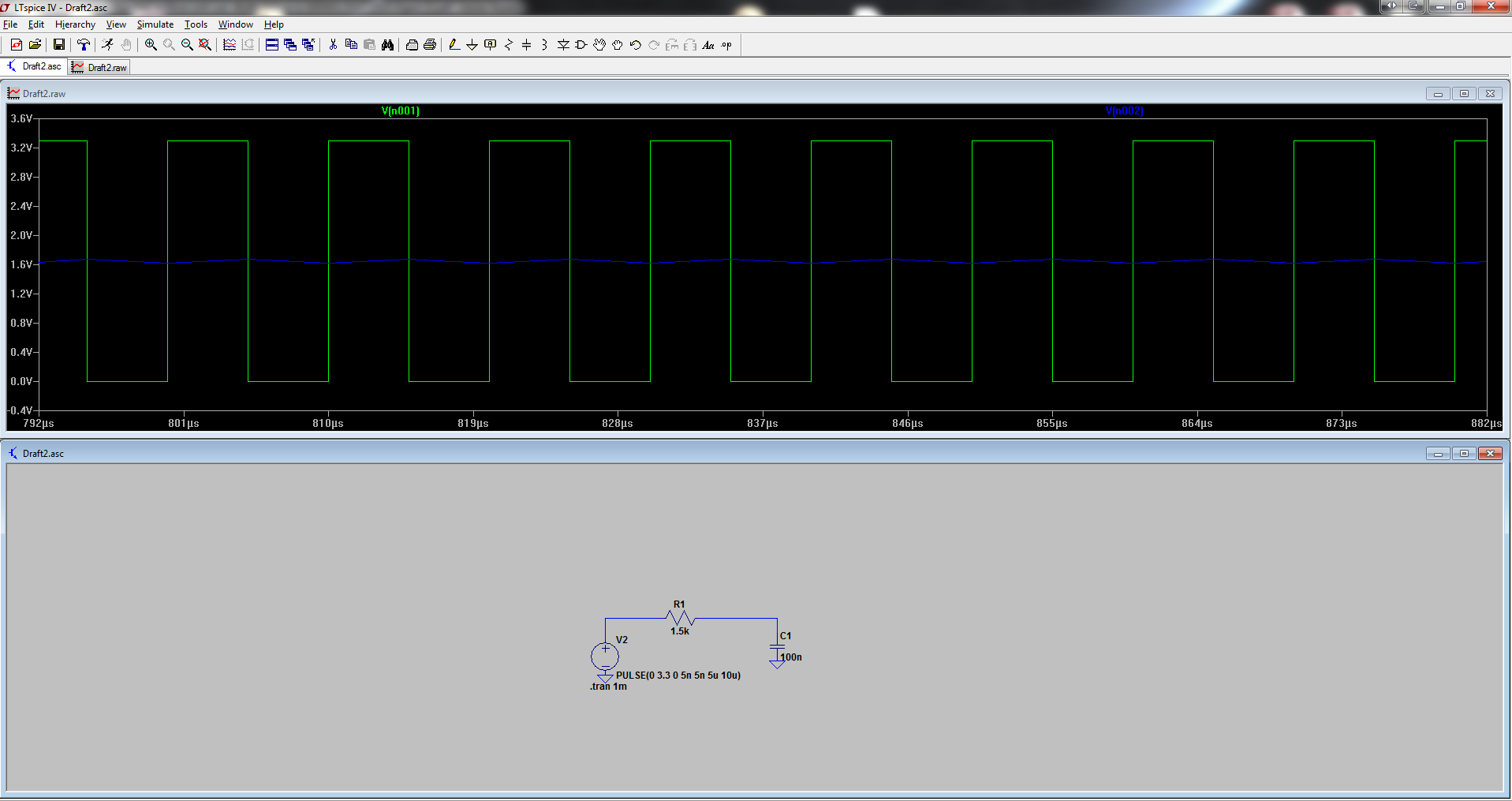
I also think a forum topic would be alot more efficient.
But I wouldn't be surprised if he indeed tries to change the pulsewidth. But if that is your goal, why use PWM in the first place? The LPC1768 has an AnalogOut, which is alot more suitable to create something like a sine, also no filtering required (or only a little bit, for sure alot less than with PWM).
But as you say, the main issue is that it is still unclear what it is exactly that he wants to make.
posted by 13 Feb 2014
.
posted by Ravneet S 13 Feb 2014