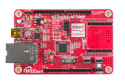
WIZwiki-W7500P
WIZwiki-W7500P is a SoC platform board based on the W7500P chip = ARM Cortex-M0 that integrates 128KB Flash and hardwired TCP/IP core and MacPhy. If you use WIZwiki-W7500 board, you can easily evaluate the W7500 and test its performance and all functions.
Overview
WIZnet WIZwiki Platform based on WIZnet's W7500P MCU. The IOP4IoT "Internet Offload Platform for IoT" W7500P chip is the SoC one-chip solution which integrates an ARM Cortex-M0, 128KB Flash and hardwired TCP/IP core & Ethernet PHY for various embedded application especially for Internet of things and Gateways. The TCP/IP core is a market-proven hardwired TCP/IP stack. If you use WIZwiki-W7500P you will be able to easily develop a prototype. It can be used as an Arduino shield because its Arduino pin Compatible. This is using the CMSIS-DAP USB and ISP Header for easy firmware writing in the mbed.org compiler environment.
Features
- WIZnet W7500P
- ARM® Cortex™-M0 Core 48MHz
- 128KB Flash memory
- 16KB to 48 KB SRAM (Min 16KB available if 32KB socket buffer is used, Max 48KB available if no socket buffer is used)
- Hardwired TCP/IP Core
- 8 Sockets
- integrated PHY IC+(IP101G)
- 12-bit, 8ch ADC
- 34 I/Os
- 1ch Watchdog, 4ch Timers and 8ch PWM
- 3ch UART
- 2ch SPI
- 2ch I2C
- Arduino form-factor
- Compatible with a wide range of commercially available shields
- Xbee Interface form-factor
- Compatible with a Xbee I/F module
- CMSIS-DAP interface firmware
- Built-in USB drag 'n' drop FLASH programmer
- USB Virtual COM port for serial terminal
- CMSIS-DAP interface for programming and debugging from offline tools
- mbed.org Developer Website
- Online Compiler
- High level C/C++ SDK
- Active developer community
Warning
- You must do not use PWM1, DUALTIMER 0(already used us ticker in mbed driver ).
- Due to low demand, Dual Edge Triggered GPIO will not be supported.
- InterruptIn class’ rise() or fall() member function will override the previous callback setting.
- As a problem with online compilers, OS 2.0 users are encouraged to replace them with OS 5.0 as shown below.

- If you want using Ethernet function with mbed OS 5.0 refer to this link : https://os.mbed.com/teams/WIZnet/code/WIZnetInterface-OS5/
Hand Book
Information
Welcome!! HANDBOOK PAGE LINK
Welcome!! COMPONENT PAGE LINK
basic examples & components example & application examples in this page Example is verified by WIZwiki-W7500P

Pinout
WIZwiki-W7500P detail Pinout

Available Pin Name at mbed
Note
Only the labels written must be used in your code. The other labels are given as information (alternate-functions, power pins, ...). You can also use these additional labels:
PA_0, PA_1, PA_2, PA_3, PA_4, PA_5, PA_6, PA_7, PA_8, PA_9, PA_10, PA_11, PA_12, PA_13, PA_14

PA_00, PA_01, PA_02, PA_03, PA_04, PA_05, PA_06, PA_07, PA_08, PA_09

PB_0, PB_1, PB_2, PB_3

PB_00, PB_01, PB_02, PB_03

PC_0, PC_1, PC_2, PC_3, PC_4, PC_5, PC_6, PC_8, PC_9, PC_10, PC_11, PC_12, PC_13, PC_14, PC_15

PC_00, PC_01, PC_02, PC_03, PC_04, PC_05, PC_06, PC_08, PC_09

A0 = PC_15, A1 = PC_14, A2 = PC_13, A3 = PC_12, A4 = PC_11, A5 = PC_10, A6 = PC_9, A7 = PC_8

D0 = PA_14, D1 = PA_13, D2 = PC_3, D3 = PC_2, D4 = PA_2, D5 = PA_1, D6 = PA_0, D7 = PA_12, D8 = PA_11, D9 = PC_1, D10 = PA_5, D11 = PA_8, D12 = PA_7, D13 = PA_6, D14 = PA_10, D15 = PA_9

LED_RED = PC_0, LED_GREEN = PC_4, LED_BLUE = PC_5

LED1 = LED_RED, LED2 = LED_GREEN, LED3 = LED_BLUE, LED4 = LED_BLUE

LEDR = LED_RED, LEDG = LED_GREEN, LEDB = LED_BLUE

USBTX = PC_10, USBRX = PC_11

SD_SEL = PB_0, SD_CLK = PB_1, SD_MISO = PB_2, SD_MOSI = PB_3
Getting Started
- How to start WIZwiki-W7500P Board
- How to install serial driver of WIZwiki-W7500P
- How to write the firmware
Update or Restore Firmware
Resources

To compile a program for this board using Mbed CLI, use wizwiki_w7500p as the target name.
Board Partner
WIZnet
WIZnet is a fabless semiconductor company specializing in Hardware TCP/IP Ethernet controller and SoC, with high performance and low cost solution.
Mbed OS support
- Mbed OS 2
- Mbed OS 5.4
- Mbed OS 5.5
- Mbed OS 5.6
Example programs