Data send-receive by IIC-bus Hardware: IIC-board with 4 x PCF8574 IC you see a 8bit leds this leds show the value from an other 8574 who has 8 switches as input The 8xswitches from IIC you can see also at the pins PC_0 to PC_7
Thats my logo Brandenkopf tower Black forest Germany:

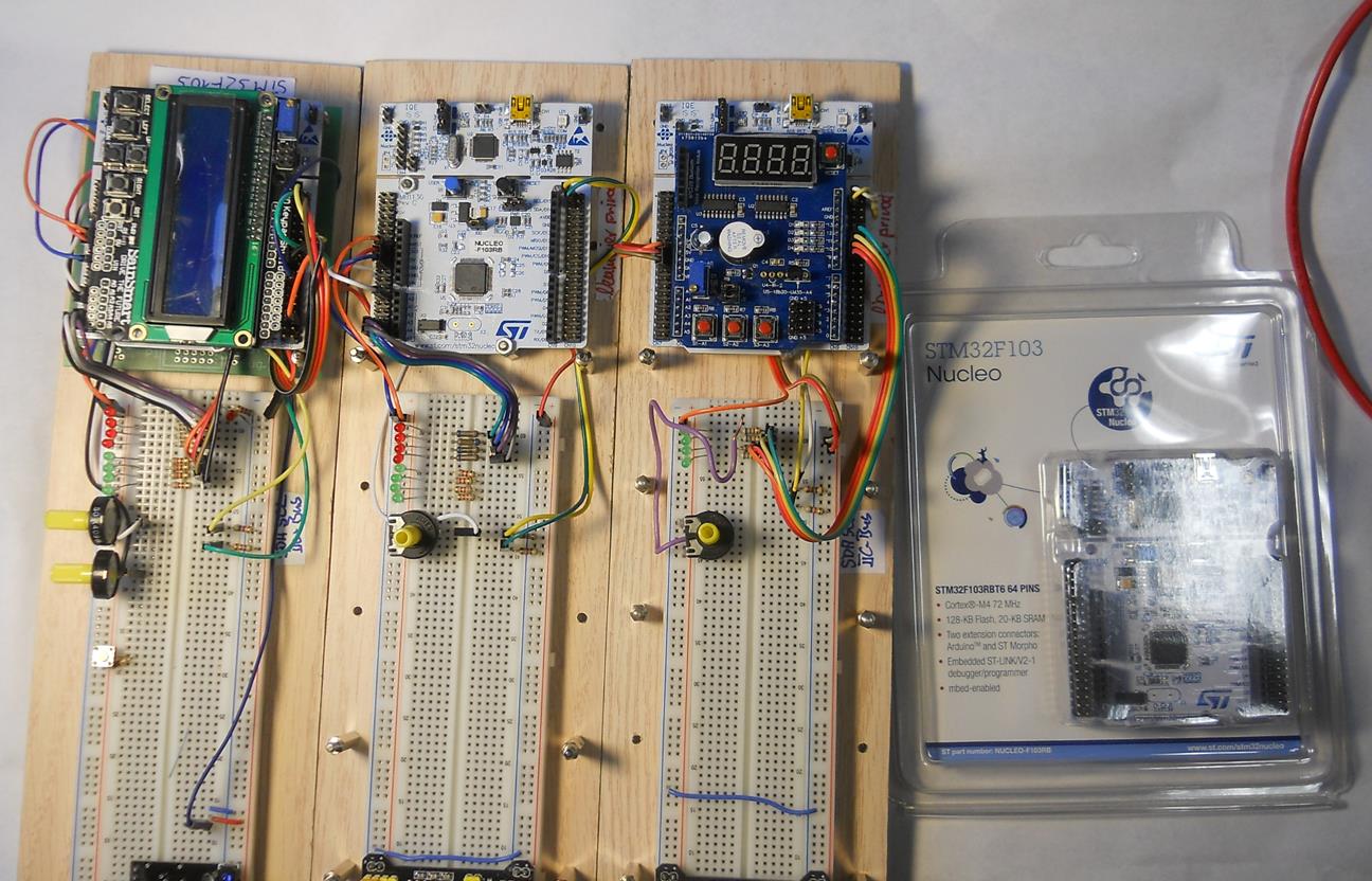
This is my hardware:

This is a farmer house in the black forest:

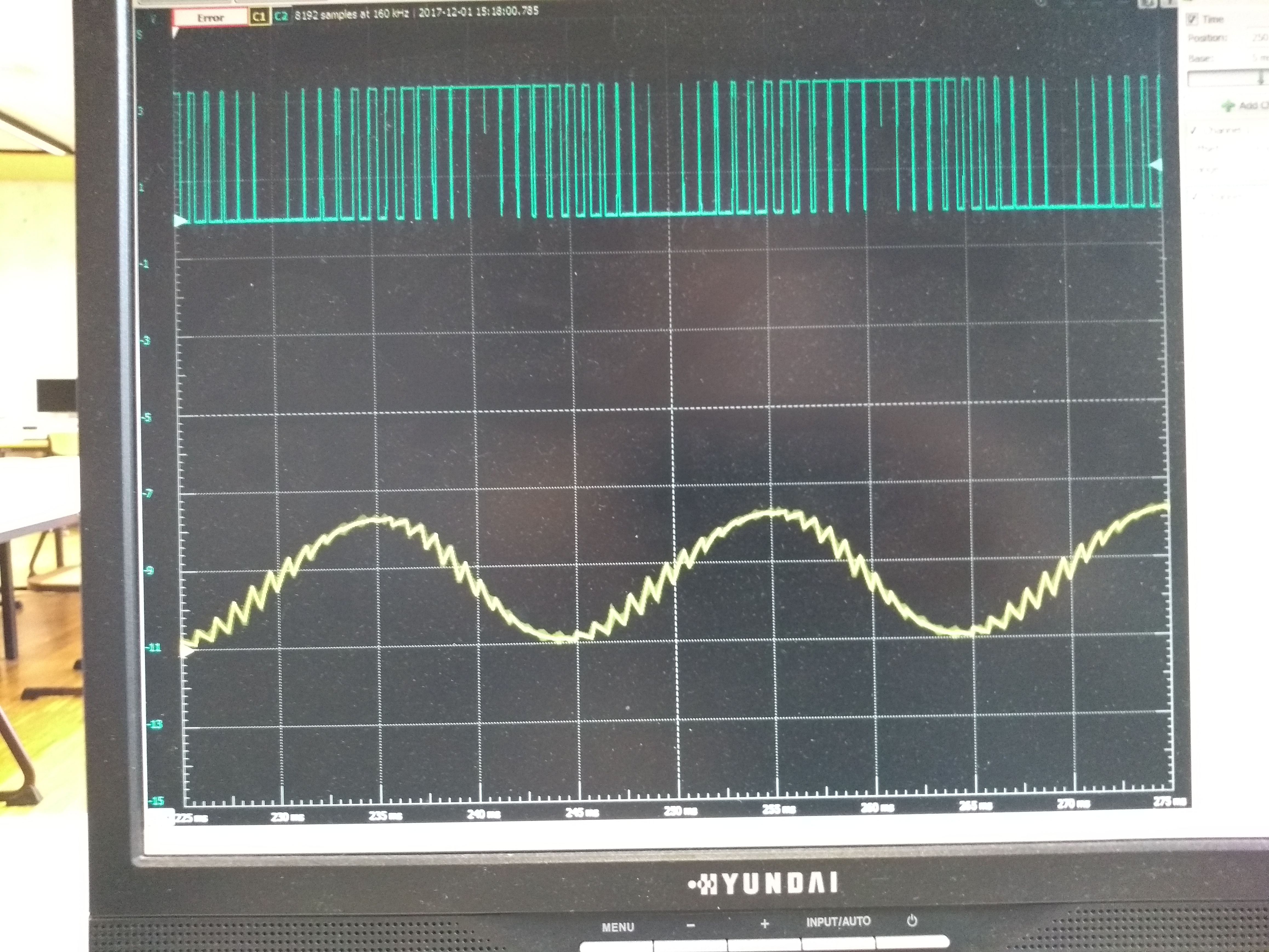
And this is a screenshot of a PWM Signal.
The sinus signal is the result whe nyou give the PWM to a R-C circuit:

And in the middle of the three grazy persons: That`s my person:

Neumaier Feb 2018
main.cpp
- Committer:
- schlaumaier54
- Date:
- 2015-08-21
- Revision:
- 0:b183e63b31f8
File content as of revision 0:b183e63b31f8:
/*Data send-receive by IIC-bus Hardware: IIC-board with 4 x PCF8574 IC
you see a 8bit leds this leds show the value from an other 8574 who has 8 switches as input
The 8xswitches from IIC you can see also at the pins PC_0 to PC_7
Tasks: 1. Receive a analog value and show this value as a 8xled-strip at the third PCF8574 IC
        2. Send the 8xswitches from IIC-bus to the virtuell COM-port. You can visualize the switches
           with the Software "Profilab" or "LABview"
Aug. 2015 G. Neumaier Gewerblich-Technische Schule Offenburg Germany
*/

#include "mbed.h"
#define PCF8574_ADDRoutput  0x46 // PCF8574 address 0x46 lowest bit (R/W)=0 IICboard P3
#define PCF8574_ADDRinput   0x45 // PCF8574 address 0x44 lowest bit (R/W)=0 IICboard P2
        //ADR-Jumper on IIC4xPCF8574board jumped to 0: Basis ADR:P0=0x40;P1=0x42;P2=0x44;P3=0x46;
       //ADR-Jumper on IIC4xPCF8574board jumped to 1: Basis ADR:P0=0x48;P1=0x4A;P2=0x4C;P3=0x4E;
#define LED_MASK  0xffff    //Portc has 16bit, therefore 4digit mask
                            // 1=output    0=input

I2C i2c(I2C_SDA, I2C_SCL); //IIC Pins SDA and SCL for ARDUINO pinheader Nucleo-board
            //SCL and SPA pullup resistors 2k2Ohm to+5Volt

PortOut leds(PortC, LED_MASK); //Important: Port_B not possible -> PB_8 PB_9 Pins for IIC-bus

DigitalOut myled(LED1); //LED on Nucleo-board
//for the task1****:  AnalogIn analog_value0(A0);      //same as Pin PA_0
//for the task2****:  Serial pc(SERIAL_TX, SERIAL_RX);

int main()
{
    char input8bit;
    char data_write[2]; //must be char!!
    char data_read[2]; //read buffer

    data_write[0] = 0xf2; //LEDs low aktiv  dummy
    int status = i2c.write(PCF8574_ADDRoutput , data_write, 1, 0);
    if (status != 0) // Error  no acknowledge detected
    {
        while (1) //-> endless loop when error no IIC-IC detected
        {
        myled = !myled;
        wait(0.7);
        }
    }

    while (1) //endless loop
        {

        // i2c.read will start the IIC-bus with the last 0 also stop the same by 12c.read
        i2c.read(PCF8574_ADDRinput, data_read, 1, 0);  // read to array  1byte  stop
        input8bit = data_read[0];   //array value to variable
        leds = input8bit; //Output PortC low-byte
        data_write[0] = input8bit;     //8bit analog-value to array
        i2c.write(PCF8574_ADDRoutput , data_write, 1, 0); //  output array 1byte  stop
        //you see a digital 8bit PCF8574 output (8xleds), received from PCF8574 input (8xswitsches)

        //Here your solutions from task1 and 2:
    }

}