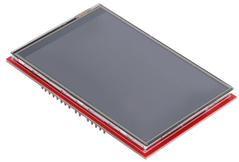
3.5" inch TFT LCD Display Module 480X320 driven with FSMC.
TFT LCD Display Module 480X320 driven with FSMC
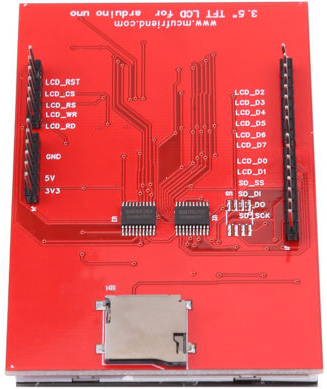
I have recently bought a 3.5" inch TFT LCD Touch Screen Display Module 480X320 with a www.mcufriend.com label on the back side. The display was equipped with an 8bit parallel interface. First I decided to test it with the UniGraphic library using the BUS_8 protocol. The display was very slow but improved when I switched to the PAR_8 protocol. Because I heard about the possibility to use a Flexible Static Memory Controller (FSMC), built into some STM MCU's, to drive LCD's (read/write to LCD's memory rather than to an external SRAM) I thought it would be a fun to try it out.

Below is the brief story of what I did:
- Created a project for my STM32F407VE board in the STM32CubeIDE
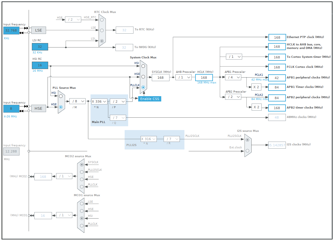
- Set the
Clock Configurationto match the one used by Mbed for the Seeed Arch Max board:
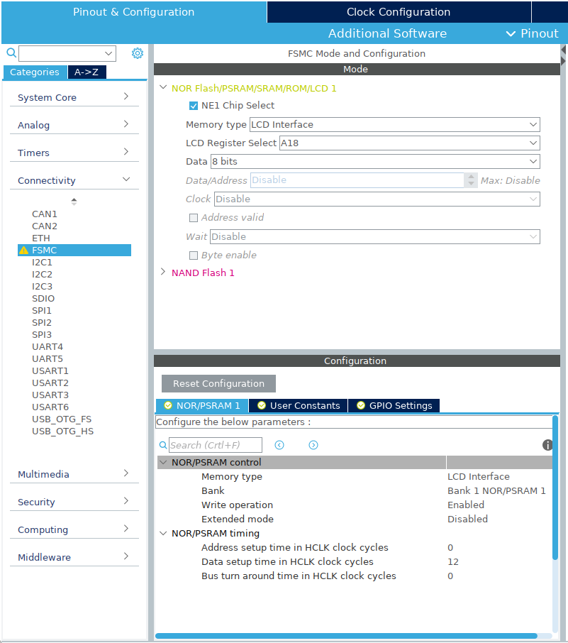
- Selected
FSMCin theConnectivitycategory and configured it as below:
- Let the
STM32CubeIDEgenerate the code (files). - Created a new program for the Seeed Arch Max target in the Mbed Online Compiler by selecting a
mbed os blinkytemplate. - Replaced the
main.cppwith themain.ccontent of theSTM32CubeIDEproject. Copy & Pastedthe other files with codes from theSTM32CubeIDEproject to the online compiler project.- Renamed and modified:
"stm32f4xx_it.h" to "stm32f4xx_it_msp.h"
"stm32f4xx_it.c" to "stm32f4xx_it_msp.c" - Added the UniGraphic library to the online compiler project.
- Extended the
UniGraphiclibrary with aFSMC_8protocol and replaced theTFT::set_orientation(int orient)function with the one used bymcufriendfor arduino. - Modified the
main.cppas needed.
 |  |
Wiring
| STM32F407VE | TFT LCD module |
|---|---|
| +3.3V | 3V3 |
| GND | GND |
| PB_12 | LCD_RST |
| GND | LCD_CS |
| PD_13 (RS) | LCD_RS |
| PD_5 (WR) | LCD_WR |
| PD_4 (RD) | LCD_RD |
| PD_14 (DB00) | LCD_D0 |
| PD_15 (DB01) | LCD_D1 |
| PD_0 (DB02) | LCD_D2 |
| PD_1 (DB03) | LCD_D3 |
| PE_7 (DB04) | LCD_D4 |
| PE_8 (DB05) | LCD_D5 |
| PE_9 (DB06) | LCD_D6 |
| PE_10 (DB07) | LCD_D7 |
Results
| Execution times | ||
|---|---|---|
| Used protocol | BUS_8 | FSMC_8 |
| Operation \ Time | ms | ms |
| Clear | 2283.980 | 38.454 |
| Plot | 192.066 | 11.365 |
| 8bit BMP | 63.805 | 41.338 |
| Large Font | 163.872 | 7.895 |
| Sparce pixels | 2072.265/1458.051 | 74.107/52.168 |
| 16bit BMP | 2288.589 | 59.904 |
UniGraphic/Protocols/SPI16.cpp
- Committer:
- hudakz
- Date:
- 2020-09-25
- Revision:
- 1:47c996032a9e
- Parent:
- 0:fa952828e34c
File content as of revision 1:47c996032a9e:
 /* mbed UniGraphic library - SPI16 protocol class
 * Copyright (c) 2015 Giuliano Dianda
 * Released under the MIT License: http://mbed.org/license/mit
 *
 * Derived work of:
 *
 * mbed library for 240*320 pixel display TFT based on ILI9341 LCD Controller
 * Copyright (c) 2013 Peter Drescher - DC2PD
 *
 * THE SOFTWARE IS PROVIDED "AS IS", WITHOUT WARRANTY OF ANY KIND, EXPRESS OR
 * IMPLIED, INCLUDING BUT NOT LIMITED TO THE WARRANTIES OF MERCHANTABILITY,
 * FITNESS FOR A PARTICULAR PURPOSE AND NONINFRINGEMENT. IN NO EVENT SHALL THE
 * AUTHORS OR COPYRIGHT HOLDERS BE LIABLE FOR ANY CLAIM, DAMAGES OR OTHER
 * LIABILITY, WHETHER IN AN ACTION OF CONTRACT, TORT OR OTHERWISE, ARISING FROM,
 * OUT OF OR IN CONNECTION WITH THE SOFTWARE OR THE USE OR OTHER DEALINGS IN
 * THE SOFTWARE.
 */

#include "SPI16.h"

SPI16::SPI16(int Hz, PinName mosi, PinName miso, PinName sclk, PinName CS, PinName reset, PinName DC)
    : _CS(CS), _spi(mosi, miso, sclk), _reset(reset), _DC(DC)
{
    _reset = 1;
    _DC=1;
    _CS=1;
    _spi.format(16,0);                  // 8 bit spi mode 0
 //   _spi.frequency(12000000);          // 10 Mhz SPI clock, 12mhz for F411
    _spi.frequency(Hz);
    hw_reset();
}

void SPI16::wr_cmd8(unsigned char cmd)
{
    _spi.format(8,0); // it takes time, better use wr_cmd16 with NOP cmd
    _DC.write(0); // 0=cmd
    _spi.write(cmd);      // write 8bit
    _spi.format(16,0);
    _DC.write(1); // 1=data next
}
void SPI16::wr_data8(unsigned char data)
{
    _spi.format(8,0); // it takes time, check prev cmd parameter, in case use wr_data16 with repeated byte
    _spi.write(data);    // write 8bit
    _spi.format(16,0);
}
void SPI16::wr_cmd16(unsigned short cmd)
{
    _DC.write(0); // 0=cmd
    _spi.write(cmd);      // write 16bit
    _DC.write(1); // 1=data next
}
void SPI16::wr_data16(unsigned short data)
{
    _spi.write(data);    // write 16bit
}
void SPI16::wr_gram(unsigned short data)
{
    _spi.write(data);    // write 16bit
}
void SPI16::wr_gram(unsigned short data, unsigned int count)
{
    while(count)
    {
        _spi.write(data);
        count--;
    }
}
void SPI16::wr_grambuf(unsigned short* data, unsigned int lenght)
{
    while(lenght)
    {
        _spi.write(*data);
        data++;
        lenght--;
    }
}
unsigned short SPI16::rd_gram(bool convert)
{
    unsigned int r=0;
    r |= _spi.write(0); // 16bit, whole first byte is dummy, second is red
    r <<= 16;
    r |= _spi.write(0);
    if(convert)
    {
        // gram is 18bit/pixel, if you set 16bit/pixel (cmd 3A), during writing the 16bits are expanded to 18bit
        // during reading, you read the raw 18bit gram
        r = RGB24to16((r&0xFF0000)>>16, (r&0xFF00)>>8, r&0xFF);// 18bit pixel padded to 24bits, rrrrrr00_gggggg00_bbbbbb00, converted to 16bit
    }
    else r >>= 8;
    _CS = 1; // force CS HIG to interupt the "read state"
    _CS = 0;

    return (unsigned short)r;
}
unsigned int SPI16::rd_reg_data32(unsigned char reg)
{
    wr_cmd8(reg);
    unsigned int r=0;

    r |= _spi.write(0); // we get only 15bit valid, first bit was the dummy cycle
    r <<= 16;
    r |= _spi.write(0);
    r <<= 1; // 32bits are aligned, now collecting bit_0
    r |= (_spi.write(0) >> 15);
    // we clocked 15 more bit so ILI waiting for 16th, we need to reset spi bus
    _CS = 1; // force CS HIG to interupt the cmd
    _CS = 0;
    return r;
}
unsigned int SPI16::rd_extcreg_data32(unsigned char reg, unsigned char SPIreadenablecmd)
{
    unsigned int r=0;
    for(int regparam=1; regparam<4; regparam++) // when reading EXTC regs, first parameter is always dummy, so start with 1
    {
        wr_cmd8(SPIreadenablecmd);  // spi-in enable cmd, 0xD9 (ili9341) or 0xFB (ili9488) or don't know
        wr_data8(0xF0|regparam);    // in low nibble specify which reg parameter we want
        wr_cmd8(reg);               // now send cmd (select register we want to read)
        r <<= 8;
        r |= (_spi.write(0) >> 8);
    }
    _CS = 1; // force CS HIG to interupt the cmd
    _CS = 0;

    return r;
}
// ILI932x specific
void SPI16::dummyread()
{
    _spi.write(0);    // dummy read
}
// ILI932x specific
void SPI16::reg_select(unsigned char reg, bool forread)
{
    _CS = 1;    //fixme: really needed?
    _CS = 0;    //fixme: really needed?
    _spi.write(0x70);   // write 0070
    _spi.write(reg);    // write 16bit
    _CS = 1;    //fixme: really needed?
    _CS = 0;    //fixme: really needed?
    if(forread) _spi.write(0x73);
    else _spi.write(0x72);
}
// ILI932x specific
void SPI16::reg_write(unsigned char reg, unsigned short data)
{
    _CS = 1;    //fixme: really needed?
    _CS = 0;    //fixme: really needed?
    _spi.write(0x70);   // write 0070
    _spi.write(reg);    // write 16bit
    _CS = 1;    //fixme: really needed?
    _CS = 0;    //fixme: really needed?
    _spi.write(0x72);   // write 0072
    _spi.write(data);   // write 16bit
}
// ILI932x specific
unsigned short SPI16::reg_read(unsigned char reg)
{
    unsigned int r=0;
    _CS = 1;    //fixme: really needed?
    _CS = 0;    //fixme: really needed?
    _spi.write(0x70);   // write 0070
    _spi.write(reg);    // write 16bit
    _CS = 1;    //fixme: really needed?
    _CS = 0;    //fixme: really needed?
    _spi.write(0x73);   // write 0073
    r |= _spi.write(0);    // read 16bit, 8bit dummy + 8bit valid
    r <<= 16;
    r |= _spi.write(0);    // read 16bit

    _CS = 1; //fixme: to resync, maybe really needed
    _CS = 0; //fixme: to resync, maybe really needed
    return (r>>8);
}
void SPI16::hw_reset()
{
    wait_ms(15);
    _DC = 1;
    _CS = 1;
    _reset = 0;                        // display reset
    wait_ms(2);
    _reset = 1;                       // end reset
    wait_ms(100);
}
void SPI16::BusEnable(bool enable)
{
    _CS = enable ? 0:1;
}