Using CAN bus with NUCLEO boards (Demo for the CANnucleo library).
Dependencies: CANnucleo mbed-dev
Dependents: BMS_2 Can_sniffer_BMS_GER Can_sniffer_bms ECU_1
Using CAN bus with NUCLEO boards
Demo for the CANnucleo library
Information
Because CAN support has been finally implemented into the mbed library also for the STM boards there is no need to use the CANnucleo library anymore (however you may if you want). See the CAN_Hello example which is trying to demonstrate the mbed built-in CAN API using NUCLEO boards.
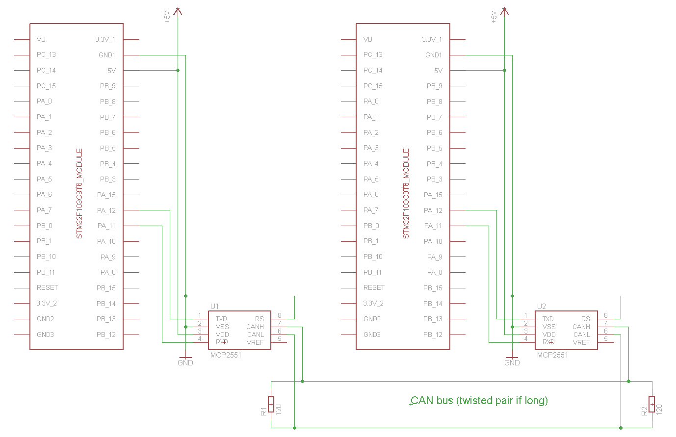
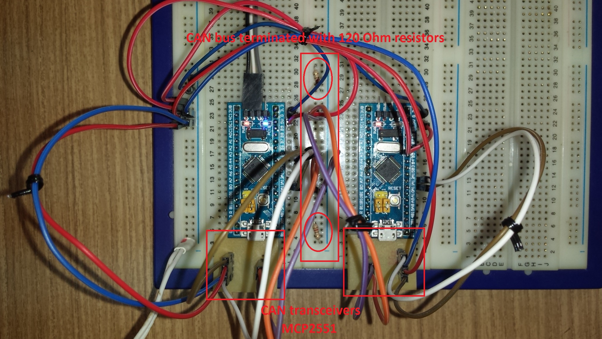
Two low cost STM32F103C8T6 boards are connected to the same CAN bus via transceivers (MCP2551 or TJA1040, or etc.). CAN transceivers are not part of NUCLEO boards, therefore must be added by you. Remember also that CAN bus (even a short one) must be terminated with 120 Ohm resitors at both ends.
Schematic

Hookup
The mbed boards in this example are transmitting CAN messages carrying two data items:
uint8_t   counter;  // one byte
float     voltage;  // four bytes
So in this case the total length of payload data is five bytes (must not exceed eight bytes).
For our convenience, the "<<" (append) operator is used to add data to the CAN message.
The usage of "<<" and ">>" operators is similar to the C++ io-streams operators. We can append data one at a time
txMsg << counter;
txMsg << voltage;
or combine all into one expression.
txMsg << counter << voltage;
The actual data length of a CAN message is automatically updated when using "<<" or ">>" operators.
After successful transmission the CAN message is printed to the serial terminal of the connected PC. So we can check the details (ID, type, format, length and raw data). If something goes wrong during transmission a "Transmission error" message is printed to the serial terminal.
On arrival of a CAN message it's also printed to the serial terminal of the connected PC. So we can see the details (ID, type, format, length and raw data). Then its ID is checked. If there is a match with the ID of awaited message then data is extracted from the CAN message (in the same sequence as it was appended before transmitting) using the ">>" (extract) operator one at a time
rxMsg >> counter;
rxMsg >> voltage;
or all in one shot
rxMsg >> counter >> voltage;
Important
Before compiling the project, in the mbed-dev library open the device.h file associated with the selected target board and add #undef DEVICE_CAN as follows:
device.h
#ifndef MBED_DEVICE_H
#define MBED_DEVICE_H

//=======================================
#define DEVICE_ID_LENGTH       24

#undef DEVICE_CAN

#include "objects.h"

#endif
NOTE: Failing to do so will result in compilation errors.
The same source code is used for both boards, but:
- For board #1 compile the example without any change to main.cpp
- For board #2 comment out the line
#define BOARD1 1before compiling
Once binaries have been downloaded to the boards, reset board #1.
NOTE:
The code published here was written for the official NUCLEO boards. When using STM32F103C8T6 boards, shown in the picture above (LED1 is connected to pin PC_13 and, via a resistor, to +3.3V),
- Import the mbed-STM32F103C8T6 library into your project.
- Include (uncomment) the line
#define TARGET_STM32F103C8T6 1 - Select NUCLEO-F103RB as target platform for the online compiler.
CAN bus related information
Diff: main.cpp
- Revision:
- 29:9ae558ec888c
- Parent:
- 28:dde6c4aef759
--- a/main.cpp	Sat Mar 11 10:14:45 2017 +0000
+++ b/main.cpp	Tue Mar 14 14:38:37 2017 +0000
@@ -20,7 +20,7 @@
  */

 #define BOARD1                1     // comment out this line when compiling for board #2
-#define TARGET_STM32F103C8T6  1     // uncomment this line when using STM32F103C8T6 boards!
+//#define TARGET_STM32F103C8T6  1     // uncomment this line when using STM32F103C8T6 boards!

 #if defined(TARGET_STM32F103C8T6)
     #include "stm32f103c8t6.h"
@@ -50,13 +50,13 @@
 CANMessage      txMsg;
 DigitalOut      led(LED_PIN);
 Timer           timer;
-uint8_t         counter = 0;
+uint8_t         counter = 0;    // one byte
 AnalogIn        analogIn(A0);
-float           voltage;
+float           voltage;        // four bytes
 volatile bool   msgAvailable = false;

 /**
- * @brief   'CAN receive-complete' interrup handler.
+ * @brief   'CAN receive-complete' interrup service routine.
  * @note    Called on arrival of new CAN message.
  *          Keep it as short as possible.
  * @param
@@ -67,7 +67,7 @@
 }

 /**
- * @brief   Prints CAN msg to PC's serial terminal
+ * @brief   Prints CAN msg to PC's serial terminal.
  * @note}
  * @param   CANMessage to print
  * @retval  none
@@ -91,17 +91,17 @@
  */
 int main() {
 #if defined(TARGET_STM32F103C8T6)
-    confSysClock();     //Configure system clock (72MHz HSE clock, 48MHz USB clock)
+    confSysClock();     //Configure the system clock (72MHz HSE clock, 48MHz USB clock)
 #endif
-    pc.baud(9600);                      // set Serial speed
+    pc.baud(9600);                      // set the Serial speed

     can = new CAN(PA_11, PA_12);        // CAN Rx pin name, CAN Tx pin name
-    can->frequency(1000000);            // set bit rate to 1Mbps
-    can->attach(&onMsgReceived);        // attach 'CAN receive-complete' interrupt handler
+    can->frequency(1000000);            // set the bit rate to 1Mbps
+    can->attach(&onMsgReceived);        // attach the 'CAN receive-complete' interrupt service routine (ISR)

 #if defined(BOARD1)
-    led = ON;       // turn LED on
-    timer.start();  // start timer
+    led = ON;       // turn the LED on
+    timer.start();  // start the timer
     pc.printf("CANnucleo_Hello board #1\r\n");
 #else
     led = OFF;      // turn LED off
@@ -110,15 +110,22 @@

     while(1) {
         if(timer.read_ms() >= 1000) {           // check for timeout
-            timer.stop();                       // stop timer
-            timer.reset();                      // reset timer
-            counter++;                          // increment counter
+            timer.stop();                       // stop the timer
+            timer.reset();                      // reset the timer
+            counter++;                          // increment the counter
             voltage = (analogIn * 3.3f)/4096.0f;// read the small drifting voltage from analog input
-            txMsg.clear();                      // clear Tx message storage
-            txMsg.id = TX_ID;                   // set ID
+            txMsg.clear();                      // clear the Tx message storage
+            txMsg.id = TX_ID;                   // set the message ID
+            // We are about to transmit two data items to the CAN bus.
+            //     counter: uint_8 (unsigned eight bits int) value (one byte).
+            //     voltage: floating point value (four bytes).
+            // So the total length of payload data is five bytes.
+            // We'll use the "<<" (append) operator to add data to the CAN message.
+            // The usage is same as of the similar C++ io-stream operators.
+            // NOTE: The data length of CAN message is automatically updated when using "<<" operators.
             txMsg << counter << voltage;        // append data (total data length must be <= 8 bytes!)
-            if(can->write(txMsg)) {             // transmit message
-                led = OFF;                      // turn LED off
+            if(can->write(txMsg)) {             // transmit the CAN message
+                led = OFF;                      // turn the LED off
                 pc.printf("-------------------------------------\r\n");
                 pc.printf("CAN message sent\r\n");
                 printMsg(txMsg);
@@ -129,18 +136,18 @@
                 pc.printf("Transmission error\r\n");
         }
         if(msgAvailable) {
-            msgAvailable = false;               // reset the flag for next use the in interrupt service routine
-            can->read(rxMsg);                   // read message into Rx message storage
-            led = ON;                           // turn LED on
+            msgAvailable = false;               // reset the flag for next use in the interrupt service routine
+            can->read(rxMsg);                   // read the message into the Rx message storage
+            led = ON;                           // turn the LED on
             pc.printf("-------------------------------------\r\n");
             pc.printf("CAN message received\r\n");
             printMsg(rxMsg);
             // Filtering performed by software:
-            if(rxMsg.id == RX_ID) {             // about filtering performed by hardware see comments in CANnucleo.cpp
-                rxMsg >> counter >> voltage;    // extract data from the received CAN message
+            if(rxMsg.id == RX_ID) {             // about filtering performed by hardware see the comments in CANnucleo.cpp
+                rxMsg >> counter >> voltage;    // extract data from the received CAN message (in same sequence as they were added)
                 pc.printf("  counter = %d\r\n", counter);
                 pc.printf("  voltage = %e V\r\n", voltage);
-                timer.start();                  // transmission lag
+                timer.start();                  // insert transmission lag
             }
         }
     }
