Shadow robot straight line motion via feedback control
Description
Sparkfun’s Shadow Robot Kit has been assembled to develop the bot and circuit has been designed to steer the bot in a straight line using IMU motion sensor for feedback control. As the bot begins to move, the Inertial Measurement Unit (IMU) passes the reading of the initial device position to the PID controller which acts as a setpoint value. Subsequently, it continually passes the compass heading readings of the device's current position as the bot moves. The controller compares current position reading with the setpoint value and tries to drive the error to zero. If there is deviation, the controller sends an output signal to adjust the speed of the left and right wheels such that the bot retains its straight line motion. For example, if the bot deviates to the right, the controller would send an error signal such that the speed of the right wheel increases and that of the left wheel decreases by an equal amount, thereby steering it left and back to the straight line path. The parameters Kp, Kd and Ki of the PID controller are tuned manually through trial and error to achieve right compensation for the motor speed. The Adafruit Bluefruit LE IC has been used for communication with the bot via bluetooth. The commands for motor start, stop, left turn, right turn, IMU calibration are given via blutetooth by pressing appropriate keys on the control pad. Also, two six volt batteries were used to power the ICs used and the two motors for left and right wheels.
Only an approximate straight line motion could be achieved due to the following challenges:
- Chassis Design - Due to design considerations, the bot could not be balanced on two wheels.The protruding chassis part on the front end of the bot opposed and interfered with movement of the wheels during test runs.
- IMU Noise - The IMU magnetometer used to take readings for feedback control had a lot of noise viz. hard iron interferences (permanent magnets in vicinity) and soft iron interferences (dc motors). Additionally, the initial orientation of sensor axis (due to tilted bot) relative to horizontal plane was unknown. Movement of the bot also caused vibrations in IMU thereby affecting its reading.
- PID Control- PID controller is “plant” dependent and to effectively tune the PID, the transfer function of the “plant” needs to be known. This would enable adoption of better tuning methods like Cohen Coon or Ziegler Nichols eliminating the need for manual tuning.
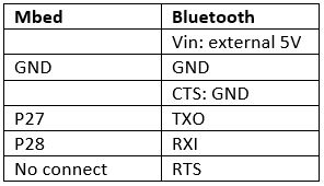
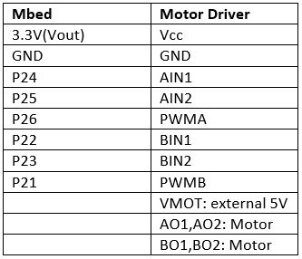
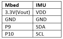
Pin Connections


Circuit Images
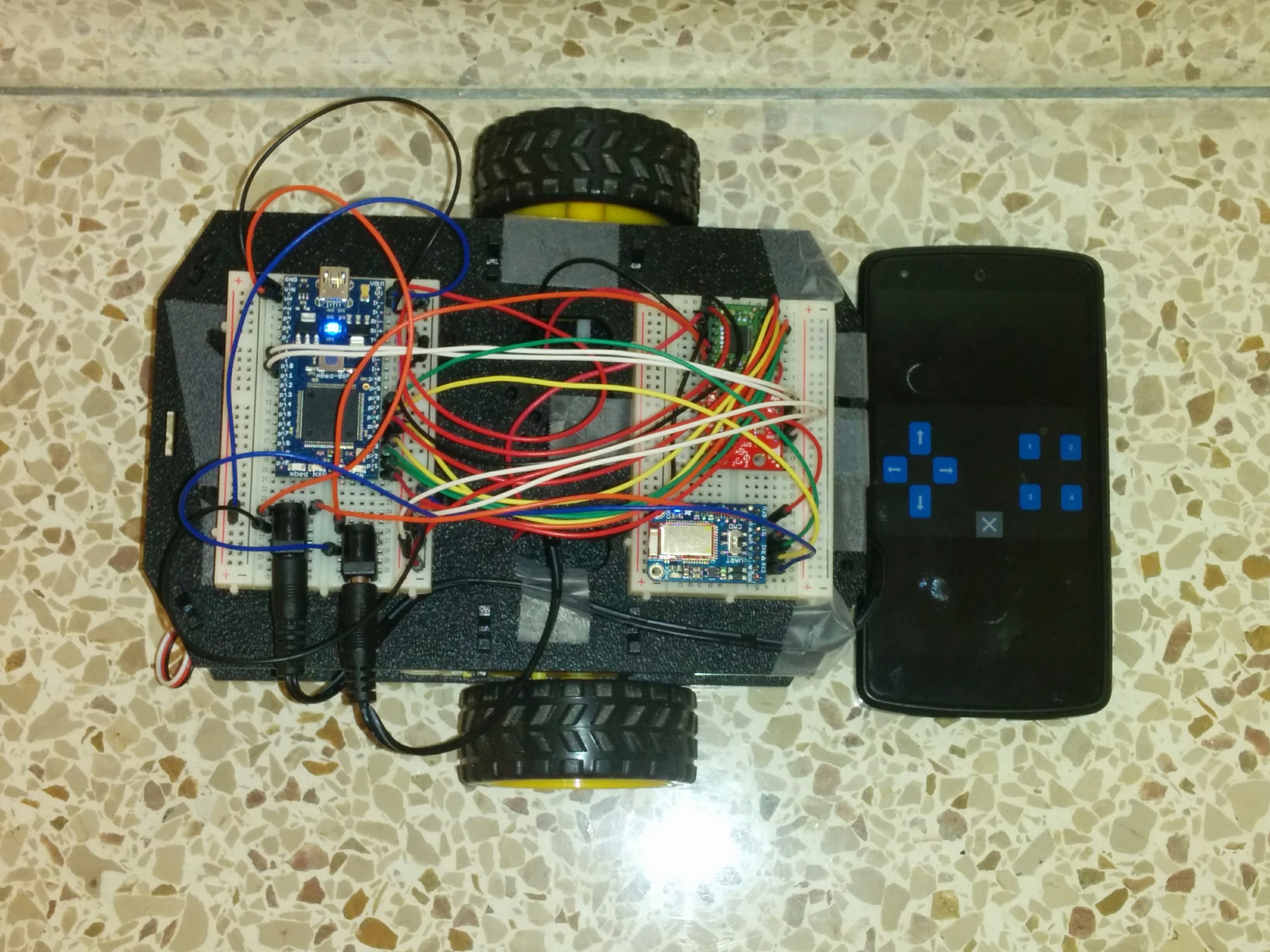
As seen in the image below, the shadow robot kit has been assembled for use with mbed and houses the physical circuit. The circuit components include LPC1768 microcontroller, LSM9DS1 IMU, TB6612FNG H-Bridge, Adafruit Bluefruit LE UART Friend and two 6V battery packs hooked to a breadboard.

Circuit Demonstration
The first video demonstrates the turn left, turn right and stop commands being given to the bot via bluetooth by pressing the arrow keys on the control pad.
The second video demonstrates the calibration of IMU and feedback controlled motion of the bot. Initially, the bot IMU is calibrated by rotating the bot through 360 degrees. Upon pressing the upward arrow key on the control pad, the bot moves. The IMU passes the readings of the compass headings of the device's current position to the PID controller. The controller then compares this reading with the setpoint value of the device's position and is tuned to drive the error to zero. Only an approximate straight line motion of the bot could be achieved using IMU and PID controller.
Code/Libraries
Robot straight line motion
#include "mbed.h"
#include "LSM9DS1.h"
#include "motordriver.h"

#define PI 3.14159
#define DECLINATION -4.94 // Declination (degrees) in Atlanta,GA.

DigitalOut myled(LED1);
BusOut myleds(LED1,LED2,LED3,LED4);
Serial pc(USBTX, USBRX);
LSM9DS1 IMU(p9, p10,0xD6, 0x3C);
Serial blue(p28,p27);
Timer t1;

//motor speed
Motor right(p21, p22, p23,0); //PinName pwm, PinName fwd, PinName rev, int brakeable
Motor left(p26, p24, p25,0); //PinName pwm, PinName fwd, PinName rev, int brakeable
float r_speed=0;
float l_speed=0;

// Calculate pitch, roll, and heading.
// Pitch/roll calculations taken from this app note:
// http://cache.freescale.com/files/sensors/doc/app_note/AN3461.pdf?fpsp=1
// Heading calculations taken from this app note:
// http://www51.honeywell.com/aero/common/documents/myaerospacecatalog-documents/Defense_Brochures-documents/Magnetic__Literature_Application_notes-documents/AN203_Compass_Heading_Using_Magnetometers.pdf
float getHeading(float mx, float my, float mz)
{
// touchy trig stuff to use arctan to get compass heading (scale is 0..360)
    mx = -mx;
    float heading;
    if (my == 0.0)
        heading = (mx < 0.0) ? 180.0 : 0.0;
    else if(my>0)
        heading = 90-atan2(mx, my)*360.0/(2.0*PI);
    else if(my<0)
        heading = 270-atan2(mx, my)*360.0/(2.0*PI);

    heading -= DECLINATION; //correct for geo location
    return heading;
}

//PI controller
//global variables
float kp=12.0f;
float ki=4.0f;
float kd=1.0f;
float P=0;
float I=0;
float D=0;
float dt=0.1f;
float out=0.0f;
float max=0.5f;
float min=-0.5f;
float prerr=0.0f;

float PI_cont(float err)
{
     float Pout=kp*err;
     P=Pout;
     //pc.printf("P is: %f \n\r",P);

     float Iout=Iout+err*dt;
     I=ki*Iout;
     //pc.printf("I is: %f \n\r",I);

     float Dout = (err - prerr)/dt;
     D=kd*Dout;

     out=P+I+D;

     prerr=err;

     //pc.printf("out is: %f \n\r",out); // basically pwm out
     if (out>max)out=max;
     else if (out<min)out=min;
     return out;
}


int main()
{
    int count=0; // variable to keep hold of the initial heading
    float SP=0; // heading set point
    float PV=0; // heading current value
    float error=0; //SP-PV
    float correction=0; // coorection to be applied to the motors

    char bnum=0;
    char bhit=0;
    while(1) {
        if (blue.getc()=='!') {
            if (blue.getc()=='B') { //button data packet
                bnum = blue.getc(); //button number
                bhit = blue.getc(); //1=hit, 0=release
                if (blue.getc()==char(~('!' + 'B' + bnum + bhit))) { //checksum OK?
                    myled = bnum - '0'; //current button number will appear on LEDs
                    switch (bnum) {

                        case '1': //number button 1
                            if (bhit=='1') {
                               myleds=15;
                            } else {
                               IMU.begin();
                               if (!IMU.begin()) {
                                    pc.printf("Failed to communicate with LSM9DS1.\n");
                                    }

                               myleds=0; // start calibrating
                               wait(1);
                               myleds=15;
                               wait(1);
                               myleds=0; // start calibrating
                               IMU.calibrate(1);
                               IMU.calibrateMag(0);
                               myleds=0; // stop calibrating
                            }
                            break;

                        case '5': //button 5 up arrow
                            if (bhit=='1') {
                                myleds=15;
                            } else {
                                myleds=0;
                                t1.start();
                                while(t1.read()<=20) {
                                    if (count==0){
                                        count++;
                                        }
                         if (count==1) {
                         while(!IMU.magAvailable(ALL_AXIS));
                         IMU.readMag();
                          SP=getHeading(IMU.calcMag(IMU.mx),IMU.calcMag(IMU.my), IMU.calcMag(IMU.mz));
                           count++;
                                     }
                                  while(!IMU.magAvailable(ALL_AXIS));
                                  IMU.readMag();
                            PV=getHeading(IMU.calcMag(IMU.mx),IMU.calcMag(IMU.my), IMU.calcMag(IMU.mz));
                            int i=1;
                                    if (PV>SP-50 && PV<SP+50)error=(SP-PV)/360; //normalized error
                                    else{
             while(PV<SP-50 || PV>SP+50 && i!=3) {
                while(!IMU.magAvailable(ALL_AXIS));
                IMU.readMag();
                PV=getHeading(IMU.calcMag(IMU.mx),IMU.calcMag(IMU.my), IMU.calcMag(IMU.mz));
                i++;
                if (i==3)error=(SP-PV)/360; //if there is no spike in magnetometer reading
                                         else{
                                                error=0; //if it is a spike
                                                r_speed=0.5;
                                                l_speed=0.5;
                                                right.speed(r_speed);
                                                left.speed(l_speed);}
                                            }
                                        }
                                    correction=PI_cont(error);//correction to motor speed
                                    if (error>2.5/360 || error<-2.5/360) {
                                        r_speed=0.5+correction;
                                        l_speed=0.5-correction;
                                        right.speed(r_speed);
                                        left.speed(l_speed);
                                        }
                                    else if (error>-2.5/360 && error<2.5/360) { //hysteresis
                                        r_speed=0.5;
                                        l_speed=0.5;
                                        right.speed(r_speed);
                                        left.speed(l_speed); }
                            }
                            t1.stop();
                        }
                            break;
                        case '6': //button 6 down arrow
                            if (bhit=='1') {
                                 myleds=15;
                            } else {
                                myleds=0;
                                r_speed=0.0f;
                                l_speed=0.0f;
                                right.stop(0);
                                left.stop(0);
                            }
                            break;
                        case '7': //button 7 left arrow
                            if (bhit=='1') {
                                 myleds=15;
                            } else {
                                myleds=0;
                                r_speed=0.5f;
                                l_speed=-0.5f;
                                right.speed(r_speed);
                                left.speed(l_speed);
                            }
                            break;
                        case '8': //button 8 right arrow
                            if (bhit=='1') {
                                 myleds=15;
                            } else {
                                myleds=0;
                                r_speed=-0.5f;
                                l_speed=0.5f;
                                right.speed(r_speed);
                                left.speed(l_speed);
                            }
                        default:
                            break;
                    }

        }
    }
}
}
}
Please log in to post comments.
