Flashing LPC1114 - ISP protocol
 Simon Carlioz.
2
replies
Simon Carlioz.
2
replies
NPX LPC1114 is a low cost microcontroller (MCU) used in lots of applications because it is cheap and it is a great chip to get started in ARM embedded development. This page will explain how to upload your code from your online compiler to the MCU's flash memory and provide examples to get you started with your device.
Here are some caracteristics of the microcontroller :
| Processor | Frequency | Flash | SRAM |
|---|---|---|---|
| ARM Cortex-M0 | Up to 50 Mhz | 32KB | 4KB |
By way of comparison, for the NPX LPC1768 :
| Processor | Frequency | Flash | SRAM |
|---|---|---|---|
| ARM Cortex-M3 | Up to 96 Mhz | 512KB | 32KB |
As long as you don't need too much flash memory, this LPC1114 might be enough for your application. But don't expect to import the RTOS library for example.

I. Theorical principle
The goal is to use the mbed online compiler to generate the code we want and then to upload it in the LCP1114's flash memory. The code that we are going to upload first is the basic example "mbed_blinky" :
LCP1114_blinky
#include "mbed.h"

DigitalOut myled(dp1);

int main() {
    while(1) {
        myled = 1;
        wait(0.2);
        myled = 0;
        wait(0.2);
    }
}
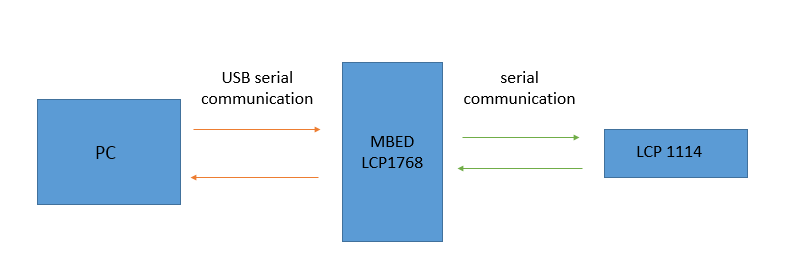
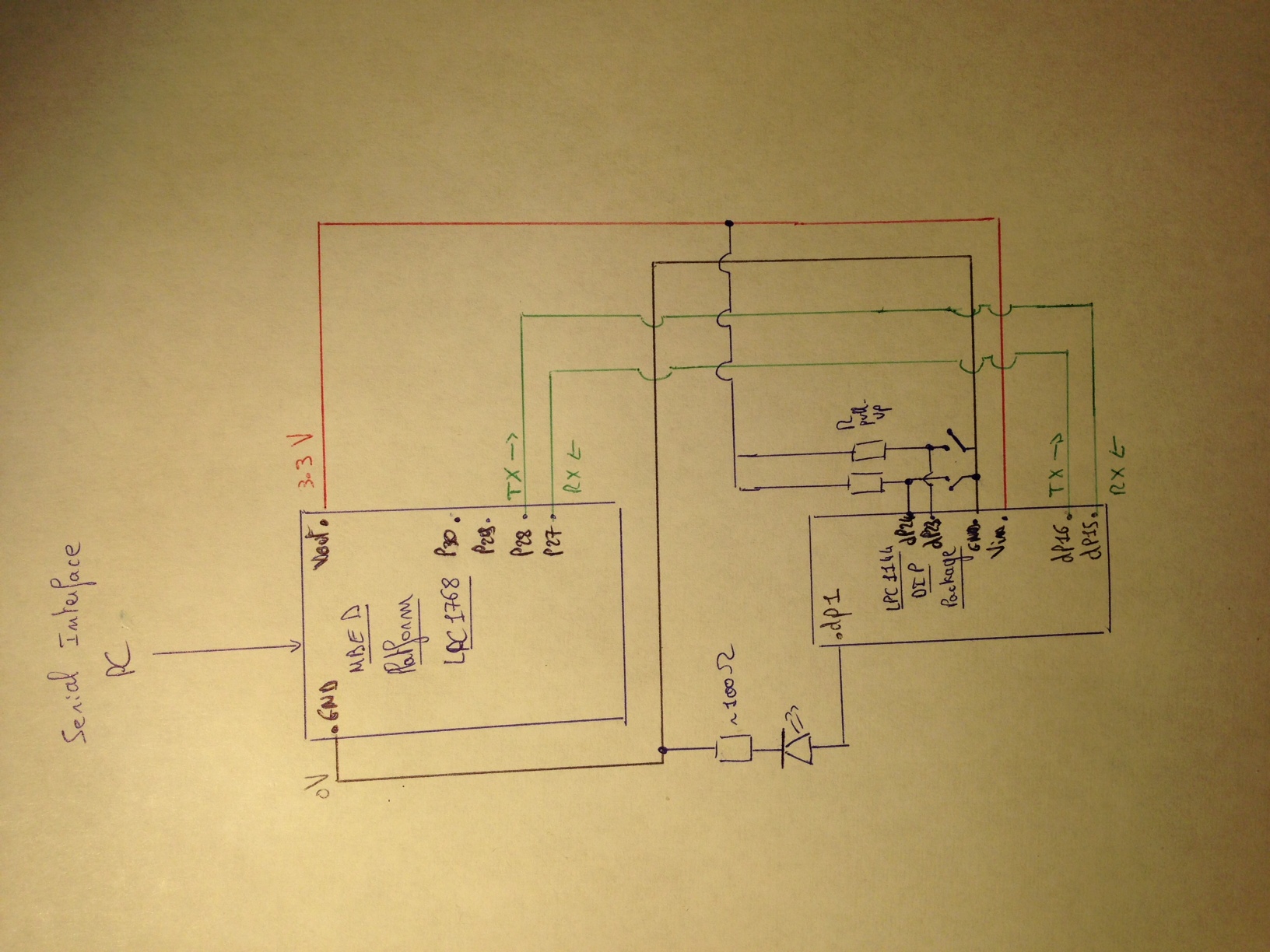
To send the commands and the code from the PC to the LCP1114, we need a Serial interface. I will use the USB interface. But, as the LCP1114 DIP package doesn't have this interface, I will use the mbed platform LCP1768 as the bridge.
To sum up, the mbed board will tranfer data from the PC to the LCP1114 and data from the LCP1114 to the PC.
The data sent to the LCP1114 need to respect a certain protocol (ISP). Otherwise, the microcontroller doesn't understand that the user (pc) want to flash it.
There are 3 main steps in this protocol :
- Initialization
- Synchronization
- Send the commands to the MCU (write, read, erase...) manually or using Flashmagictool
Information
Don't forget to select the right board on the online mbed compiler. If you were using another platform before, you will have an error because the name and/or the number of the pins don't match...
II. General notions
What is ISP (In-System Programming)?
ISP is the ability of some programmable logic devices, microcontrollers, and other embedded devices to be programmed while installed in a complete system, rather than requiring the chip to be programmed prior to installing it into the system.
What code to upload in the mbed board to interface the PC and the LCP1114?
mbed_ISP
#include "mbed.h"

DigitalOut led1(LED1);
DigitalOut led2(LED2);

Serial pc (USBTX,USBRX); //communication with the computer
Serial target (p28,p27); //communication with the LPC1114

int main() {

    pc.baud(9600);
    target.baud(9600);

    while (1) {

        if (pc.readable()) {
            target.putc(pc.getc()); //Transfer data from the PC to the target
            led1 = !led1;
        }

        if (target.readable()) {  //Transfer data from the target to the PC
            pc.putc(target.getc());
            led2 = !led2;
        }

    }
}
Now your interface between the computer and the LPC1114 is set and you can start the ISP protocol.
Information
Note that we do not need the mbed plateform to flash the LPC1114. A USB Breakout board like this one can also be used. If you do so, you obviously don't need to load the code in your mbed bord...
How to initialize the ISP protocol?
The idea is that you have to tell the MCU you want to use the ISP mode. The user manual explains you how to do this (chapter 26, p414).
- The firt thing is to reset the processor (dp23 LOW) to launch the bootloader. The bootloader code is executed every time the part is powered on or reset. The bootloader controls initial operation after reset and also provides the means to accomplish programming of the flash memory via UART or C_CAN. This could be initial programming of a blank device, erasure and re-programming of a previously programmed device, or programming of the flash memory by the application program in a running system.
- After reset, a LOW level at the PIO0_1 pin (dp24) is considered as an external hardware request to start the ISP command handler either via UART or C_CAN, if present. Assuming that power supply pins are on their nominal levels when the rising edge on RESET pin is generated, it may take up to 3 ms before PIO0_1 is sampled and the decision whether to continue with user code or ISP handler is made.
Now the MCU knows that you are going to flash it and waits for synchrosization and commands.
Information
We could include this initialization step in the code of the mbed and link dp23 and dp24 pin of the LPC1114 to digital outputs of the mbed board. But imagine you have already loaded a code in your target and the target uses the serial port (with a printf for example). If you want now to re-initialise and re-synchronize your target to write a new code on its flash memory, you will have on one hand the PC trying to send data to the target and on the other hand the target executing its current code. You might have conflicts. To avoid that, I will use push-buttons to make the initialization step manually.
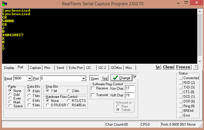
How to synchronize ?
This step is described as well in the user manual (26.3.3, p417).
- Send "?" to the serial port. The target will answer by "Synchonized"
- Send "Synchronized" in response. You should receive "OK"
- Send the crystal frequency (in KHz) "50000" for example which is the maximum frequency for this MCU. You will receive "OK"

The synchronisation is now finished, you can now send commands to the MCU
Information
If you want to learn how to send data on the serial port you can refer to the SerialPC Handbook.
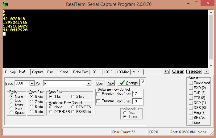
What command to send to the LCP1114?
Once again, you can refer to the user manual for an exhaustive list of commands (26.5, p424).
Here are some examples :
| Command | To be sent |
|---|---|
| Unlock | U <Unlock Code> |
| Write to RAM | W <start address> <number of bytes> |
| Read Memory | R <address> <number of bytes> |
| Read the unique ID | N |
| Read Part ID | J |
| Read Boot code version | K |
| ... | ... |
Note that we need to use the "Unlock" command before using flash "Write", "Erase", and "Go" commands.
We are now, in theory, able to write all the code we need in the MCU ! But it wouldl take way too much time to write the program manually...
Flashmagictool can do it for you.
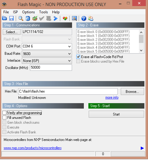
How to use Flashmagictool ?
Flashmagitool will do the synchronization and the commands for you, but you still have to do the "initialization" step.
You just have to load the code (file in hexadecimal ie .hex), set up some parameters (MCU type,COM port, Baud rate, Frequency) and
click on start!
It's magic...
.hex file!
It could have been all, but indeed, we are not done yet....
When we compile our LPC1114_blinky from the online compiler, it is not a hexadecimal file. It's a binary file...
We have to convert it!
Binary to hexadecimal conversion
BIN2HEX is one of these file converter :
- Download the .exe
- Unzip it in a directory called flash in C:\
- Copy the .bin file in this same directory
- Rename it "flash" (or as you like but if you choose a long name, it will be longer to type the command in the command prompt)
- Open your cmd and enter the following instruction to launch the conversion :
C:\flash> bin2hex.exe flash.bin flash.hex
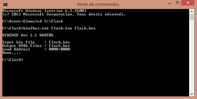
Your hexadecimal file is created in the "C:\flash" directory. You can now use Flashmagictool
Information
If you have never used the the command prompt, your might need some basic commands:
- "dir" show all the files in the current directory
- "cd.." change to the parent directory
- "cd C:\flash" change to C:\flash
III. In practical
We're now done with the theory, we can hook up our components
Pinning information
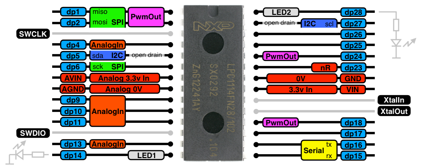
You can also take a look at the datasheet (chapter 6, p11).
The hardware
- 1 NXP LCP1114 (the target)
- 1 Mbed platform LPC1768
- 1 external LED 2.2V and one resistor (100 Ohms)
- 2 push-buttons and 2 pull-up resistors (2.2 KOhms or more)
| LPC1768 | LPC1114 |
|---|---|
| Vout | Vin |
| GND | GND |
| p28 (TX) | dp15 (RX) |
| p27(RX) | dp16(TX) |
| LPC1114 | Other Devices |
|---|---|
| dp1 | LED |
| dp23 | Reset push-button |
| dp24 | ISP push-button |
Information
- The size of the .hex file for this small program is 24.1 KB and we only have 32 KB of Flash. This shows that the memory space will be the main issue when using this MCU.
- Note that the target doesn't know when flashmagictool has finished to upload the code. Therefore, the target won't execute the code by itselft. We need to click on the reset button to make the led blinking.
- You can also notice that flashmagictool take some time to upload the code to the target. This is because of the baudrate. You can try to change it and you will see the difference. The fastest I could go was 115200 bps.
IV. To go further
Libraries' size
You can now test the limit of the memory by uploading bigger codes. For example, you can try to use other libraries than "mbed.h".To get an order of magnitude of the size of each library, I converted this code into a hexadecimal file :
#include "XXX.h"

int main() {
}
| Librairies | Size of the file |
|---|---|
| "mbed.h" | 1.81 KB |
| "rtos.h"+"mbed.h" | 33.2 KB |
| ""HTU21D.h"+"mbed.h" | 1.81KB |
Power Consumption
I also wanted to compare the power consumption of the LPC1114 compared to the one of the mbed board when they ran the same program using a temperature and humidity sensor (HTU21D) :
mbed_HTU21D
#include "mbed.h"
#include "HTU21D.h"

Serial pc(USBTX,USBRX); //Serial communication with the PC
HTU21D sensor(p9,p10 ); // Temp module (sda, SCL)
DigitalOut led ( p20);

int main(){
    led=1;
    pc.baud(115200);
    pc.printf("Hello LPC1114 world! \r\n");

    while(1){
        pc.printf("Current humidity : %i  \r\n", sensor.sample_humid());
        wait(5);
        }
}
| Device | Voltage | Current | Power |
|---|---|---|---|
| LPC1114 | 3.3V | 20mA | 66mW |
| mbed board | 4.5V | 180mV | 810mW |
Information
The comparison would have been more accurate if i had have the LCP1768 DIP package only and not the LCP1768 incorporated in the mbed board
5) References
2 comments on Flashing LPC1114 - ISP protocol:
Please log in to post comments.
Flashing LPC1114 - ISP protocol
Page owner: Simon Carlioz
Created 17 Oct 2014.
Last updated 29 Oct 2014
Bin to Hex programm, see: https://www.dropbox.com/s/1ee4w0h6x1qhpaf/PORTUGUES_BIN2HEXGUI.exe?dl=0 This is a borland program,
/media/uploads/strain11/portugues_bin2hexgui.exe