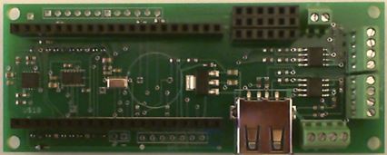
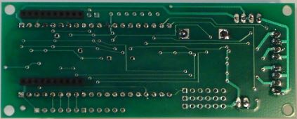
SCIboard(TM): mbed base board data logger - Altimeter: MPL3115A2 - Accelerometer: LSM303DLHC - Gyro: L3G4200D - 4 High Current MOSFET switches


Product Description
SCIboard will take your model rocketry, science, or engineering project to new heights with a complete 10-Degree-Of-Freedom (10-DOF) Inertial Measurement Unit (IMU), 4 high current MOSFET switches, PWM interface (RC servos), USB (memory sticks or BlueTooth) and interfaces for GPS and an XBee® RF module. The SCIboard is an mbed base board ideal for use in college and high school science labs, science fair projects, high power model rocketry, model airplanes, and near space balloon projects. SCIboard is also designed for Open Source software so you can customize the application. Example applications include high power model rocketry, near space balloon projects, and R/C airplanes/quadcopters. While SCIboard requires some basic electronics and software knowledge, it combines multiple breakout boards into a single base board which improves reliability, especially in high g environments such as in model rocketry. Available on Amazon. Search on "SCIboard".
- Dimensions: 1.5 x 3.8 inches (3.8 x 9.7 cm)
- Weight: 0.8 ounces (24 g)
10-DOF Inertial Measurement Unit
Going beyond just the 6 degrees of freedom afforded by a 3-axis accelerometer and 3-axis gyro, SCIboard includes an additional 3-axis magnetometer, and highly accurate altimeter / atmospheric pressure sensor. Sensors provide digital measurements over an I2C shared bus (p27 and p28).
Precision Altimeter
(Freescale Semiconductor – MPL3115A2) MEMS pressure sensor with 24-bit Analog-to-Digital Converter (ADC) employs temperature compensation resulting in fully compensated 20-bit pressure/altitude measurements (resolution down to 1 foot).
- Pressure range: 50 – 110 kPa.
- Pressure reading noise: 1.5 Pa RMS over -10 to +70° C. Conversion rate: up to 100 Hz.
- 12-bit temperature sensor measurement range: -40 to +85° C.
3-Axis MEMS Accelerometer
(STMicroelectronics – LSM303DLHC) The sensor measures linear acceleration. Pointing any axis to the earth will apply 1 g in that axis when stationary.
- Selectable full scale range: +/-2 g to +/-16 g.
- Sensitivity: 1 – 12 mg/LSB depending on full scale range.
- Zero-g level offset: +/-60 mg.
- Acceleration noise density: 220 micro-g/sqrt(Hz).
- Operating temp range: -40 to +85° C.
- Conversion rate up to 400 Hz.
3-Axis Ultra-Stable MEMS Gyroscope
(STMicroelectronics – L3G4200D) A gyroscope is an angular rate sensor.
- Selectable full scale ranges: 250/500/2000 degrees per second (DPS).
- Resolution: 16-bit.
- Bandwidth: user selectable.
- Sensitivity: 8.75/17.50/70 milli-degrees per second/LSB.
- Nonlinearity: 0.2% full scale
- Rate noise density: 0.03 DPS/sqrt(Hz).
- Operating temp range: -40 to +85°C.
Digital I/O
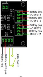
4 MOSFET switches are included. They provide 6-amperes momentary current sinking. Example uses include high power strobes, and lights for night launches or buzzers for location. Switches can be activated at apogee or prior to landing for model rocketry. A continuity check through an analog to digital converter allows verification of circuit continuity before launch. A piezoelectric buzzer provides software control for audible alert and low battery voltage measurement.

Host USB Type-A with 5.0 Vdc regulator
USB Type-A connector wired as a host controller provides regulated 5 volt power from a battery. A variety of USB devices from memory sticks, Bluetooth, and Wi-Fi can be used with multiple software projects from the mbed web site.
XBee® and XBee-PRO® Modules
The XBee-PRO® interface supports multiple different XBee and XBee-PRO modules such as Wi-Fi, ZigBee, 802.15.4, Bluetooth, and longer range 900 MHz RF Modules. Compatible modules are Roving Networks and Digi-International. SCIboard provides dual 10 pin headers with regulated 3.3 volt power (from p40) and serial UART (Tx=p9/Rx=p10). Alternatively if the headers are not installed, the serial port may be connected to a SMS cell phone evaluation module. Since the 3.3 volt provided to XBee modules is from the mbed regulator, the user is responsible for power calculations. Testing was done with RN-XV and a 9-volt battery but higher battery voltages or higher current XBee modules could overheat the 3.3 volt regulator on the mbed. When using XBee modules, the user may need to perform hard/soft iron calibration if using the magnetometer.
Interface for GPS
SCIboard provides a serial UART interface for GPS receivers. It also provides 3.3 and 5.0 Vdc for power and Vbat (battery not included). PCB has 0.1” holes for soldered cable or header of your choice. This provides flexibility to use a variety of GPS modules.

Interface for Ethernet Cable
PCB has 0.1” interface for an Ethernet cable of your choice of Ethernet magnetics interface with LEDs. For Ethernet direct wire, use RD-, RD+, TD+, and TD-. For magnetics, several 3.3 Vdc and Grounds are provided allowing easy interfacing. For both LEDs a 160 ohm resistor is provided. Both LEDs share the 2 PWMs out.

Interface for PWM RC Servos
SCIboard provides a Pulse Width Modulation (PWM) header for RC servo motors. Up to 6 PWM servos can be controlled. Terminal block is provided for separate servo power source if desired. If the user chooses to not install the headers, the PCB has 0.1” spacing thru-holes for 3-pin R/C servos. (Pins 21 – 26)

Applications
A 10-Degree-Of-Freedom Inertial Measurement Unit (IMU) can be used to measure distance traveled, velocity, acceleration, attitude (yaw, pitch, and roll), and attitude rate. When combined with a GPS, SCIboard will provide a GPS aided inertial navigation solutions. The PWM can be used to control a camera attached to a servo motor. This enables near space projects to point the camera up at the weather balloon, horizontally at the earth’s horizon, and down directly at the earth.
- College and high school science labs
- Science Fairs
- High Power Model Rocketry
- Near Space Balloons
- Quadcopters
- R/C Airplanes
- R/C Helicopter
Processor Board Support (Direct Pin-Out compatible)
- mbed LPC1768
- mbed LPC11U24
- Embedded Artists LPCexpresso LPC1769
SCIboard_MPL3115A2.h@5:dc778a682d29, 2014-04-06 (annotated)
- Committer:
- AstrodyneSystems
- Date:
- Sun Apr 06 19:03:29 2014 +0000
- Revision:
- 5:dc778a682d29
- Parent:
- 1:a54c4a4f3b30
Added ublox GPS
Who changed what in which revision?
| User | Revision | Line number | New contents of line |
|---|---|---|---|
| AstrodyneSystems | 1:a54c4a4f3b30 | 1 | /* SCIboard(TM) MPL3115A2.h |
| AstrodyneSystems | 1:a54c4a4f3b30 | 2 | Copyright (c) 2013 K. Andres |
| AstrodyneSystems | 1:a54c4a4f3b30 | 3 | |
| AstrodyneSystems | 1:a54c4a4f3b30 | 4 | Permission is hereby granted, free of charge, to any person obtaining a copy |
| AstrodyneSystems | 1:a54c4a4f3b30 | 5 | of this software and associated documentation files (the "Software"), to deal |
| AstrodyneSystems | 1:a54c4a4f3b30 | 6 | in the Software without restriction, including without limitation the rights |
| AstrodyneSystems | 1:a54c4a4f3b30 | 7 | to use, copy, modify, merge, publish, distribute, sublicense, and/or sell |
| AstrodyneSystems | 1:a54c4a4f3b30 | 8 | copies of the Software, and to permit persons to whom the Software is |
| AstrodyneSystems | 1:a54c4a4f3b30 | 9 | furnished to do so, subject to the following conditions: |
| AstrodyneSystems | 1:a54c4a4f3b30 | 10 | |
| AstrodyneSystems | 1:a54c4a4f3b30 | 11 | The above copyright notice and this permission notice shall be included in |
| AstrodyneSystems | 1:a54c4a4f3b30 | 12 | all copies or substantial portions of the Software. |
| AstrodyneSystems | 1:a54c4a4f3b30 | 13 | |
| AstrodyneSystems | 1:a54c4a4f3b30 | 14 | THE SOFTWARE IS PROVIDED "AS IS", WITHOUT WARRANTY OF ANY KIND, EXPRESS OR |
| AstrodyneSystems | 1:a54c4a4f3b30 | 15 | IMPLIED, INCLUDING BUT NOT LIMITED TO THE WARRANTIES OF MERCHANTABILITY, |
| AstrodyneSystems | 1:a54c4a4f3b30 | 16 | FITNESS FOR A PARTICULAR PURPOSE AND NONINFRINGEMENT. IN NO EVENT SHALL THE |
| AstrodyneSystems | 1:a54c4a4f3b30 | 17 | AUTHORS OR COPYRIGHT HOLDERS BE LIABLE FOR ANY CLAIM, DAMAGES OR OTHER |
| AstrodyneSystems | 1:a54c4a4f3b30 | 18 | LIABILITY, WHETHER IN AN ACTION OF CONTRACT, TORT OR OTHERWISE, ARISING FROM, |
| AstrodyneSystems | 1:a54c4a4f3b30 | 19 | OUT OF OR IN CONNECTION WITH THE SOFTWARE OR THE USE OR OTHER DEALINGS IN |
| AstrodyneSystems | 1:a54c4a4f3b30 | 20 | THE SOFTWARE. |
| AstrodyneSystems | 1:a54c4a4f3b30 | 21 | */ |
| AstrodyneSystems | 1:a54c4a4f3b30 | 22 | |
| AstrodyneSystems | 1:a54c4a4f3b30 | 23 | #ifndef __SCIboard_MPL3115A2_H |
| AstrodyneSystems | 1:a54c4a4f3b30 | 24 | #define __SCIboard_MPL3115A2_H |
| AstrodyneSystems | 1:a54c4a4f3b30 | 25 | |
| AstrodyneSystems | 1:a54c4a4f3b30 | 26 | #include "mbed.h" |
| AstrodyneSystems | 1:a54c4a4f3b30 | 27 | #include "SCIboard_I2C.h" |
| AstrodyneSystems | 1:a54c4a4f3b30 | 28 | |
| AstrodyneSystems | 1:a54c4a4f3b30 | 29 | // Freescale Semiconductor www.freescale.com - I2C Precision Altimeter |
| AstrodyneSystems | 1:a54c4a4f3b30 | 30 | // Data sheet Rev 2.2 07/2012 |
| AstrodyneSystems | 1:a54c4a4f3b30 | 31 | #define MPL3115A2_I2C_ADDR (0x60<<1) |
| AstrodyneSystems | 1:a54c4a4f3b30 | 32 | |
| AstrodyneSystems | 1:a54c4a4f3b30 | 33 | // Altimeter registers |
| AstrodyneSystems | 1:a54c4a4f3b30 | 34 | #define ALTREG_STATUS 0x00 |
| AstrodyneSystems | 1:a54c4a4f3b30 | 35 | #define ALTREG_OUT_P_MSB 0x01 |
| AstrodyneSystems | 1:a54c4a4f3b30 | 36 | #define ALTREG_OUT_T_MSB 0x04 |
| AstrodyneSystems | 1:a54c4a4f3b30 | 37 | #define ALTREG_DR_STATUS 0x06 |
| AstrodyneSystems | 1:a54c4a4f3b30 | 38 | #define ALTREG_WHO_AM_I 0x0C |
| AstrodyneSystems | 1:a54c4a4f3b30 | 39 | #define ALTREG_SYSMOD 0x11 |
| AstrodyneSystems | 1:a54c4a4f3b30 | 40 | #define ALTREG_PT_DATA_CFG 0x13 |
| AstrodyneSystems | 1:a54c4a4f3b30 | 41 | #define ALTREG_CTRL_REG1 0x26 |
| AstrodyneSystems | 1:a54c4a4f3b30 | 42 | #define ALTREG_CTRL_REG2 0x26 |
| AstrodyneSystems | 1:a54c4a4f3b30 | 43 | #define ALTREG_CTRL_REG3 0x28 |
| AstrodyneSystems | 1:a54c4a4f3b30 | 44 | #define ALTREG_CTRL_REG4 0x29 |
| AstrodyneSystems | 1:a54c4a4f3b30 | 45 | #define ALTREG_CTRL_REG5 0x2A |
| AstrodyneSystems | 1:a54c4a4f3b30 | 46 | |
| AstrodyneSystems | 1:a54c4a4f3b30 | 47 | // Altimeter oversampling value and minimum time between sample - Ratio x 4 ms + 2 ms |
| AstrodyneSystems | 1:a54c4a4f3b30 | 48 | // Min time between samples |
| AstrodyneSystems | 1:a54c4a4f3b30 | 49 | #define OS1 0 // 6 ms |
| AstrodyneSystems | 1:a54c4a4f3b30 | 50 | #define OS2 1 // 10 ms |
| AstrodyneSystems | 1:a54c4a4f3b30 | 51 | #define OS4 2 // 18 ms |
| AstrodyneSystems | 1:a54c4a4f3b30 | 52 | #define OS8 3 // 34 ms |
| AstrodyneSystems | 1:a54c4a4f3b30 | 53 | #define OS16 4 // 66 ms |
| AstrodyneSystems | 1:a54c4a4f3b30 | 54 | #define OS32 5 // 130 ms |
| AstrodyneSystems | 1:a54c4a4f3b30 | 55 | #define OS64 6 // 258 ms |
| AstrodyneSystems | 1:a54c4a4f3b30 | 56 | #define OS128 7 // 512 ms |
| AstrodyneSystems | 1:a54c4a4f3b30 | 57 | |
| AstrodyneSystems | 1:a54c4a4f3b30 | 58 | // Altimter modes |
| AstrodyneSystems | 1:a54c4a4f3b30 | 59 | #define ALT_MODE 1 |
| AstrodyneSystems | 1:a54c4a4f3b30 | 60 | #define BAR_MODE 0 |
| AstrodyneSystems | 1:a54c4a4f3b30 | 61 | |
| AstrodyneSystems | 1:a54c4a4f3b30 | 62 | class SCIboard_MPL3115A2 |
| AstrodyneSystems | 1:a54c4a4f3b30 | 63 | { |
| AstrodyneSystems | 1:a54c4a4f3b30 | 64 | public: |
| AstrodyneSystems | 1:a54c4a4f3b30 | 65 | SCIboard_MPL3115A2(SCIboard_I2C *ptr_I2C); |
| AstrodyneSystems | 1:a54c4a4f3b30 | 66 | unsigned char getDeviceID(void); |
| AstrodyneSystems | 1:a54c4a4f3b30 | 67 | void setMode(unsigned char mode, unsigned char overSampling); |
| AstrodyneSystems | 1:a54c4a4f3b30 | 68 | void OST(void); |
| AstrodyneSystems | 1:a54c4a4f3b30 | 69 | bool bDataAvailable(void); |
| AstrodyneSystems | 1:a54c4a4f3b30 | 70 | unsigned char getDrStatus(void); |
| AstrodyneSystems | 1:a54c4a4f3b30 | 71 | unsigned char getSysmod(void); |
| AstrodyneSystems | 1:a54c4a4f3b30 | 72 | void getData(float *rtn); |
| AstrodyneSystems | 1:a54c4a4f3b30 | 73 | |
| AstrodyneSystems | 1:a54c4a4f3b30 | 74 | private: |
| AstrodyneSystems | 1:a54c4a4f3b30 | 75 | SCIboard_I2C *pI2C; |
| AstrodyneSystems | 1:a54c4a4f3b30 | 76 | unsigned char recallMode; |
| AstrodyneSystems | 1:a54c4a4f3b30 | 77 | }; |
| AstrodyneSystems | 1:a54c4a4f3b30 | 78 | |
| AstrodyneSystems | 1:a54c4a4f3b30 | 79 | #endif |
 SCIboard mbed base board