Important changes to repositories hosted on mbed.com
Mbed hosted mercurial repositories are deprecated and are due to be permanently deleted in July 2026.
To keep a copy of this software download the repository Zip archive or clone locally using Mercurial.
It is also possible to export all your personal repositories from the account settings page.
You are viewing an older revision! See the latest version
Homepage
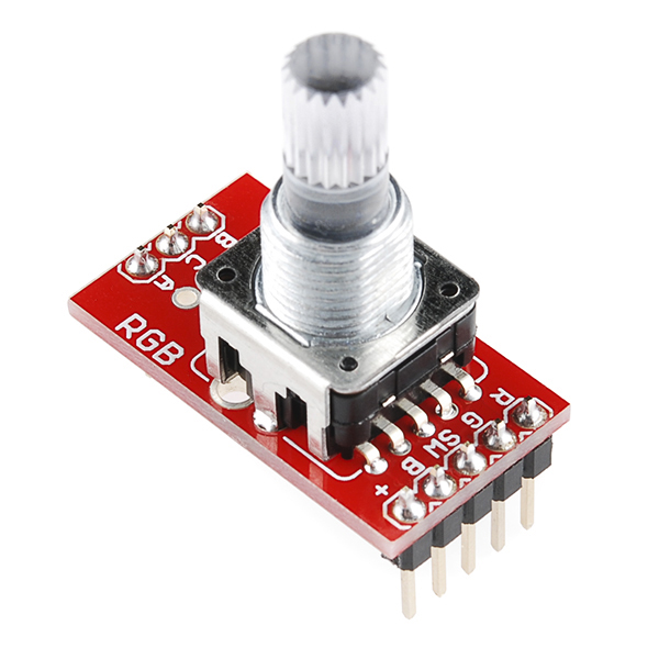
This is a demo for Sparkfun's RPG (rotary pulse generator) with an internal RGB led using interrupts to read the encoder signal. See comments in main.cpp for more details and pin hookups. The RPG is mounted on Sparkfun's breakout board. The code uses the encoder count to dim the built-in red LED using PWM. The RPG's shaft pushbutton is also debounced using interrupts.
While simple software polling (programmed I/O) could be used to read the encoder bits, interrupts are more efficient in this application since it would be necessary to sample and read the two encoder bits a couple hundred times a second when someone spins the knob. Since the vast majority of the time bits are not changing at all, constantly polling this fast wastes a lot of processor time and power!


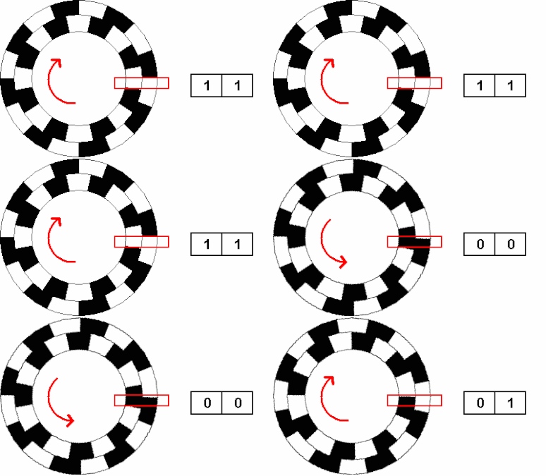
Encoder animation of A and B output bits from Wikipedia

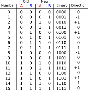
The encoder uses Gary code (only 1 bit changes at a time), if no bits or two bits change it may be switch contact noise and the count is not changed (i.e., a "0") in the truth table. See http://makeatronics.blogspot.com/2013/02/efficiently-reading-quadrature-with.html for a detailed explanation of the RPG encoder counting algorithm using interrupts with a lookup table.
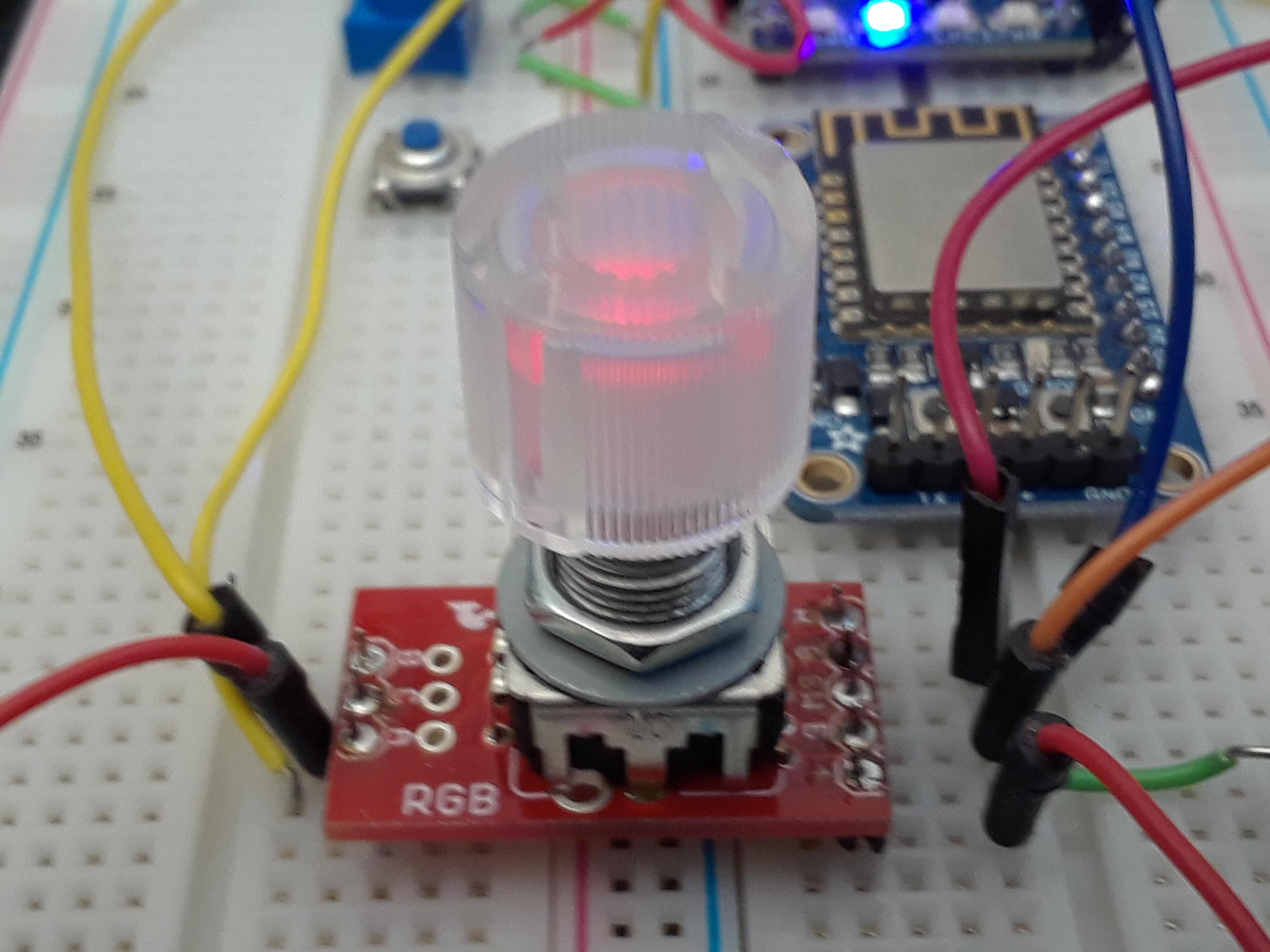
The header pins are spaced so far apart that all of the jumper wire pins are under the PCB in the normal breadboard locations for an IC, but if you put in across a power bus (power bus under middle of PCB) as seen in the photo below, you will have room to connect the jumper wires after inserting the breakout (otherwise pins for jumper wires are all under the breakout board).

Parts used:
https://www.sparkfun.com/products/15141 https://www.sparkfun.com/products/11722 https://www.sparkfun.com/products/10597
Wiring
| RPG breakout | mbed LPC1768 |
|---|---|
| A encoder output bit | p14 |
| B encoder output bit | p15 |
| C | gnd |
| + | Vout |
| R LED- | p21 |
| G LED- | p22 |
| B LED- | p23 |
| SW pushbutton | p16 |
This same scheme of two phase shifted encoder output bits to determine CW or CCW rotation is often used for feedback in motor control systems. In this application, it is called a quadrature encoder (QE). The mbed LPC1768 has a built-in hardware quadrature encoder interface with a counter that would be nice to use for the RPG, but it does not come out on the module's limited breadboard pins.