802.15.4 DIOs, ADCs and PWM example for mbed XBeeLib By Digi
This example shows how to handle remote XBee modules DigitalInputOutputs, ADCs and PWMs. The example configures the remote XBee module pins to the desired functionality and then operates on those pins.
See Handling remote modules DIOs ADCs and PWMs chapter for more information.
Common Setup
Make sure you have a valid Example Common Setup
Example Setup
Application
You have to configure the remote device 64-bit address by customizing the REMOTE_NODE_ADDR64_MSB and REMOTE_NODE_ADDR64_LSB defines with the remote XBee module 64-bit address.
Hardware
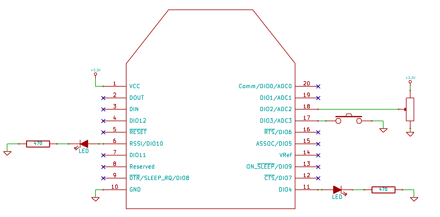
On the Remote XBee module, wire following peripherals to the pins specified on the table and schematics or change the application pins according to your hardware setup:
| Line | Pin | Value |
|---|---|---|
| DIO2/ADC2 | 18 | ADC (Analog Input) |
| DIO3/ADC3 | 17 | Digital Input |
| RSSI/DIO10 | 6 | PWM (Analog Output) |
| DIO4 | 11 | Digital Output |

Running the example
Build and deploy the example to the mbed module.
Reset the mbed module so the example starts. You should see the example debug information through the debug interface configured in the 'Local Setup' chapter.
The application will do following operations:
- Configure the remote XBee module pins according to the table above.
- Do following loop every 5 seconds:
- Read DIO3_AD3 digital value
- Toggle LED associated to DIO4_AD4
- Read DIO2_AD2 analog value
- Set the led associated to PWM0 to different intensity levels
main.cpp
- Committer:
- hbujanda
- Date:
- 2016-07-29
- Revision:
- 10:5f5bb759a57e
- Parent:
- 9:01e90da5b15d
File content as of revision 10:5f5bb759a57e:
/**
 * Copyright (c) 2015 Digi International Inc.,
 * All rights not expressly granted are reserved.
 *
 * This Source Code Form is subject to the terms of the Mozilla Public
 * License, v. 2.0. If a copy of the MPL was not distributed with this file,
 * You can obtain one at http://mozilla.org/MPL/2.0/.
 *
 * Digi International Inc. 11001 Bren Road East, Minnetonka, MN 55343
 * =======================================================================
 */

#include "mbed.h"
#include "XBeeLib.h"
#if defined(ENABLE_LOGGING)
#include "DigiLoggerMbedSerial.h"
using namespace DigiLog;
#endif

#define REMOTE_NODE_ADDR64_MSB  ((uint32_t)0x0013A200)

#error "Replace next define with the LSB of the remote module's 64-bit address (SL parameter)"
#define REMOTE_NODE_ADDR64_LSB  ((uint32_t)0x01234567)

#define REMOTE_NODE_ADDR64      UINT64(REMOTE_NODE_ADDR64_MSB, REMOTE_NODE_ADDR64_LSB)

using namespace XBeeLib;

Serial *log_serial;

int main()
{
    log_serial = new Serial(DEBUG_TX, DEBUG_RX);
    log_serial->baud(9600);
    log_serial->printf("Sample application to demo how to handle remote XBee802 devices DIOs, ADCs and PWMs\r\n\r\n");
    log_serial->printf(XB_LIB_BANNER);

#if defined(ENABLE_LOGGING)
    new DigiLoggerMbedSerial(log_serial, LogLevelInfo);
#endif

    XBee802 xbee = XBee802(RADIO_TX, RADIO_RX, RADIO_RESET, NC, NC, 9600);

    RadioStatus radioStatus = xbee.init();
    MBED_ASSERT(radioStatus == Success);

    const RemoteXBee802 remoteDevice = RemoteXBee802(REMOTE_NODE_ADDR64);

    radioStatus = xbee.set_pin_config(remoteDevice, XBee802::DIO3_AD3, DigitalInput);
    MBED_ASSERT(radioStatus == Success);

    radioStatus = xbee.set_pin_pull_up(remoteDevice, XBee802::DIO3_AD3, true);
    MBED_ASSERT(radioStatus == Success);

    radioStatus = xbee.set_pin_config(remoteDevice, XBee802::DIO4_AD4, DigitalOutHigh);
    MBED_ASSERT(radioStatus == Success);

    radioStatus = xbee.set_pin_config(remoteDevice, XBee802::DIO2_AD2, Adc);
    MBED_ASSERT(radioStatus == Success);

    radioStatus = xbee.set_pin_config(remoteDevice, XBee802::PWM0, Pwm);
    MBED_ASSERT(radioStatus == Success);

    while(true) {
        IOSample802 ioSample = xbee.get_iosample(remoteDevice);

        if (!ioSample.is_valid()) {
            log_serial->printf("get_iosample failed, ADC and Digital Input reads will be invalid\r\n");
        }

        /* Read DIO3_AD3 digital value */
        DioVal dio3_val;
        radioStatus = ioSample.get_dio(XBee802::DIO3_AD3, &dio3_val);
        MBED_ASSERT(radioStatus == Success);
        log_serial->printf("DIO3 value = %d\r\n", dio3_val);

        /* Toggle LED associated to DIO4_AD4 */
        static bool led_on = false;
        log_serial->printf("Setting DIO4 to = %d\r\n", led_on);
        if (!led_on)
            radioStatus = xbee.set_dio(remoteDevice, XBee802::DIO4_AD4, Low);
        else
            radioStatus = xbee.set_dio(remoteDevice, XBee802::DIO4_AD4, High);
        MBED_ASSERT(radioStatus == Success);
        led_on = !led_on;

        /* Read DIO2_AD2 analog value */
        uint16_t adc2_val;
        radioStatus = ioSample.get_adc(XBee802::DIO2_AD2, &adc2_val);
        MBED_ASSERT(radioStatus == Success);
        log_serial->printf("ADC2 value = 0x%04x\r\n", adc2_val);

        /* Set the led associated to PWM0 to different intensity levels */
        static float pwm_val_list[] = { 0.0, 50.0, 70.0, 100.0 };
        static uint8_t pwm_val_idx = 0;
        log_serial->printf("Setting PWM0 to = %f\r\n", pwm_val_list[pwm_val_idx]);
        radioStatus = xbee.set_pwm(remoteDevice, XBee802::PWM0, pwm_val_list[pwm_val_idx]);
        MBED_ASSERT(radioStatus == Success);
        pwm_val_idx++;
        if (pwm_val_idx == sizeof(pwm_val_list)/sizeof(pwm_val_list[0])) {
            pwm_val_idx = 0;
        }

        log_serial->printf("\r\n");

        wait(5);
    }

    delete(log_serial);
}
 Digi International Inc.