RHOMBIO L476DMW1K
IoT kit based on Rhomb.io modular system, ready to build electronic devices out-of-the-box. Arm® Pelion™ Device Ready certification already available.
Overview
RHOMBIO_L476DMW1K is a kit which consists of four rhomb.io boards that are ready to build electronic end-devices, this kit runs Arm® Mbed™ OS and also has Arm® Pelion™ Device Ready certification.
The kit is composed of:
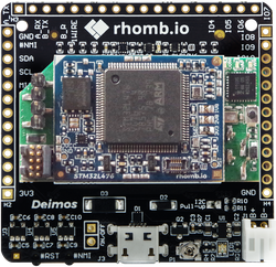
- Deimos Carrier board
- STM32L476 Master module
- ESP8266 Slave module (WiFi)
- DAPter module (DAPlink interface)
Deimos carrier board is a multi-platform ready-for-product board, with a reduced form factor and Li-Ion battery charger. It has three sockets available: one for a Master module and two for Slave modules, allowing multiple combinations with a number of peripherals/sensors. Also, up to 44 I/O and power pins are accessible for easy connection to a wide range of peripherals.
STM32L476 Master module is a powerful MCU module based on an ultra-low power Cortex-M4+FPU running up to 80MHz. External QSPI, secure element and USB switch are also included.
ESP8266 Slave module, based on the popular and certified WiFi module by Espressif.
DAPter module is a removable DAPlink interface, a great tool for flashing and debugging rhomb.io Master modules.
The kit is designed for both development purposes and inclusion in complete end-devices ready to be connected to cloud computing platforms. In addition, there is the possibility of adding any type of rhomb.io Slave modules like communications, sensing, storage or any other modules from the catalog. The kit is ready to build, program and install in your product. All kit's boards are 100% compliant with the rhomb.io ecosystem.
Assemble your own kit
Microcontroller features
- STM32L476VGT6 in LQFP100 package
- ARM®32-bit Cortex®-M4 with FPU and ART accelerator
- 80 MHz max CPU frequency
- VDD from 1.71V to 3.6 V
- 1 MB Flash
- 128 KB SRAM
- GPIOs (114) with external interrupt capability
- 12-bit ADCs with 16 channels (3)
- 12-bit DAC channels (2)
- USART (3)
- UART (2)
- LPUART (1)
- SAI (2)
- I2C (3)
- SPI (3)
- Quad SPI (1)
- Advance control Timer (2)
- General purpose Timer (7)
- Basic Timer (2)
- Low-power Timer (2)
- Watchdog Timers (2)
- CAN (1)
- USB OTG FS
- SDMMC
- SWPMI
- LCD COM x SEG
- Random generator (TRNG for HW entropy)
- Capacitive sensing (21)
- Analog comparator (2)
- Operational amplifier (2)
STM32L476 Master module features
- STSTM32L476VGT6, 32-bit ARM Cortex-M4 & FPU
- 80 MHz & 32 KHz, 1 MB Flash, 128 KB SRAM
- External Memory 16 MB QSPI Flash Memory
- Secure element 16 Keys/ECDSA/ECDH/SHA-256/SMAC/NIST
- ID Memory 64-bit Unique-ID Memory with 112 B User EEPROM
- Other Native USB OTG & USB switch; JTAG/SWD micro connector
- Rhomb.io Config. 2xUSB, 3xUART, SPI, 2xI2C, SDIO, QSPI, SAI, CAN, 4xINT, 5xPWM, 26xGPIO, 8xAD
- MCU I/O 82xI/O (12xPWM, 16xADC, 16xINT, 2xSAI, SDIO, QSPI, CAN)
- Op. Voltage 1.8 V / 2.8 V / 3.3 V
- Op. Temperature -40 ºC to +85 ºC


Deimos Carrier board features
- Multi-platform ready-for-product board
- 1x S200 Master rhomb.io socket and 2x Slave rhomb.io sockets
- IP67 enclosure available
- 44 signals brought to 2.54 mm headers
- UART switch
- Reset and User buttons
- Input power: USB connector and solder pads
- 3 LDOs: 3.3V@600mA, 2.8V@300mA, 1.8V@300mA
- Battery connector
- Battery charger with potentiometer: 15 to 500 mA
- 64-bit Unique-ID Memory with 112 B User EEPROM
- Op. voltage: 1.8 V to 5.5 V
- Op. temperature: -25 ºC to +85 ºC
- Dimensions: 50x49.5 mm


ESP8266 Slave module features
- Espressif ESP8266EX, 32-bit Tensilica L106, 80-160 MHz
- 4 MB Flash, 50 KB SRAM
- 64-bit Unique-ID Memory with 112 B User EEPROM (optional)
- 802.11b/g/n 2.4 GHz, up to 72.2 Mbps; FCC/CE(RED)/TELEC(MIC)/KCC/SRRC/IC/NCC; WPA/WPA2
- WEP/TKIP/AES
- UART, SPI, I2C, 2xINT, 5xGPIO
- 12xI/O (4xPWM, 11xINT)
- 2.8 V / 3.3 V
- -40 ºC to +85 ºC


DAPter module features
DAPter module is a DAPlink interface for Rhomb.io Master modules. Commonly referred to as interface firmware, DAPLink runs on a secondary MCU, the NXP Semiconductors' LPC11U35 microcontroller, that is attached to the SWD port of the target MCU. It creates a bridge between your development computer and the target's debug access port.
What makes the DAPter module stand out against other DAPlink applications, is that it can be used on any rhomb.io device, it doesn't matter if it is an early prototype or a product in mass production. Just click the Adapter module between the compatible Master module and the motherboard and as soon as it its turned on, it has all DAPlink capabilities.
DAPter module provides developers with:
- Drag-and-drop programming (MSC)
- Virtual serial port (CDC)
- CMSIS-DAP based debugging (HID)


DAPter can be reprogrammed at any time by plugging it in with the button held down. This will cause it to appear as a "CRP Disabled" drive.
Click here to find out more on how to use a DAPlink interface!
Furthermore, on the DAPter module, the user can find a 4-position DIP switch at the bottom-right corner on top. These small switches allow the user to set different configurations of the device.

Switch position 1 corresponds to the USB_SW_S signal.
| [1] | USB interfaces to connectors distribution |
|---|---|
| 0 | DAPLink interface -> microUSB connector; Master USB interface -> H3 |
| 1 | DAPLink interface -> H3; Master USB interface -> microUSB connector |
Switch position 2 corresponds to the #UART_SW_OE signal, switch position 3 corresponds to the #UART_SW_S signal.
| [2] | [3] | Active UART interface |
|---|---|---|
| 0 | 0 | COMP-A |
| 0 | 1 | UART-C |
| 1 | 0 | UART-B |
| 1 | 1 | UART-A |
Switch position 4 corresponds to the DBG_TG_S signal.
| [4] | Selected target for 10-pin cortex connector |
|---|---|
| 0 | Master module |
| 1 | DAP interface |
Switch 1 allows to swap the functionalities of the USB connector on a carrier board and the 4-pin header on the DAPter.
When switch is in position 0, then DAPLink interface will be accessible through the on-board microUSB connector and Master module USB interface will be accessible through the H3 4-pin header on Adapter module.
When switch is in position 1, Master module USB interface will be accessible through the on-board microUSB connector and DAPLink interface will be accessible through the H3 4-pin header on Adapter module.
Switch 2 selects the state of the two switch ICs of the UART interfaces (inverted), and switch 3 selects which position of those switches becomes available.
By using switches 2 and 3, the active UART interface between the Master module and the DAPLink interface can be selected between UART-A, UART-B, UART-C and COMP-A.
Finally, switch 4 allows the user to choose what is connected to the 10-pin cortex connector, either the DAP interface MCU (e.g.: for firmware updating) or the Master module (e.g.: external debugging of an STM32 with ST-Link, J-Link...).
NOTE: Please note that by default, all DIP switch positions are set to 0.
NOTE 2: Please note that for this kit, the UART interface that should be used is COMP-A, which corresponds to STM32L476's PC_4 and PC_5 pins.
DAPter's firmware
Latest version of DAPter's firmware (v251): lpc11u35_dapter_rhombio_l476dmw1k_if_crc_v1.2.bin
Kit pinout


Technical references
For more information, please refer to:
- STM32L476VG microcontroller
- RHOMBIO_L476DMW1K IoT Kit
- Deimos Carrier board
- STM32L476 Master module
- ESP8266 Slave module
- DAPter module
Known limitations
The following section describes known limitations of the platform. Note that general issues are tracked into the mbed repository available on GitHub.
This platform does not present any limitation.
Getting started
You will need to build your kit up before start coding, if not done yet:
DAPter and ESP8266 modules must be plugged on Deimos board while STM32L476 module must be plugged on top or DAPter board
- There is a small white triangle on the upper-left corner of any socket on any rhomb.io carrier board
- There is a small white triangle on the upper-left corner of any rhomb.io module
- Take your Deimos carrier board upside up and look for the small white triangle located on the upper-left corner of Master module socket
- Take your DAPter board and look for its small white triangle, now plug it on top of Deimos board firmly
- Do the same with STM32L476 Master module and plug it on top of DAPter board
- Now take your Deimos board upside down and look for the small white triangle located on the upper-left corner of Slave module socket 1
- Take your ESP8266 module and plug it on said Slave module socket 1
- Make sure all three modules have been plugged firmly and properly
You are now ready to connect your RHOMBIO-L476DMW1K to a PC. Take a USB cable and plug it on both the PC and the Deimos' USB connector, the kit should be detected by the computer as both Mass Storage Device, MSD, and Serial Port (COM/tty)
Now you can drag & drop any .bin file compiled with Mbed OS to the MSD assigned by the PC to your DAPter (e.g: D:\). The mbed-os-example-blinky is a great sample code to get started with your RHOMBIO_L476DMW1K and Arm mbed-os.
Try compiling said example and then drag & drop the resulted binary file into the MSD. The two LEDs available on board will start blinking at the same time. Open a serial terminal at 9600 bauds and see all messages being sent by the kit.
Example applications
[Repository '/teams/mbed-os-examples/code/mbed-os-example-blinky/' not found]
Import programpelion-example-rhombio-l476dmw1k
Mbed OS and Pelion Device Management example over WIFI for RHOMBIO_L476DMW1K IoT kit
Last commit 22 May 2019 by ![]() rhomb.io
rhomb.io
You need to log in to post a discussion
To compile a program for this board using Mbed CLI, use RHOMBIO_L476DMW1K as the target name.
Silicon Partner
ST
A world leader in providing the semiconductor solutions that make a positive contribution to people’s lives, both today and in the future.
 Mbed Enabled
- Advanced
- Baseline
Mbed OS support
- Mbed OS 5.11
- Mbed OS 5.12
- Mbed OS 5.13
- Mbed OS 5.14
- Mbed OS 5.15
- Mbed OS 6.0
- Mbed OS 6.1
- Mbed OS 6.10
- Mbed OS 6.11
- Mbed OS 6.12
- Mbed OS 6.13
- Mbed OS 6.14
- Mbed OS 6.15
- Mbed OS 6.2
- Mbed OS 6.3
- Mbed OS 6.4
- Mbed OS 6.5
- Mbed OS 6.6
- Mbed OS 6.7
- Mbed OS 6.8
- Mbed OS 6.9
Example programs