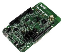
FRDM-KW41Z
The FRDM-KW41Z is a low cost development platform for Kinetis® KW41Z, KW31Z, and KW21Z MCUs.
RF Software in Development
Please note that support for the following features of FRDM-KW41Z are currently in development in mbed OS. Schedule for release is TBD.
- Bluetooth Low Energy
- 802.15.4 (Thread)
Overview
The FRDM-KW41Z has been designed by NXP in collaboration with mbed for prototyping all sorts of devices, especially those requiring the size and price point offered by Cortex-M0+. The board is well sized for low-power applications, thanks to its power efficient Kinetis KW41Z MCU featuring an ARM® Cortex®-M0+ core running up to 48MHz and embedding 512KB Flash, 128KB RAM. Features on FRDM-KW41Z include but not limited to a 32 MHz reference oscillator crystal, RF circuitry (including antenna), 4-Mbit external serial flashflash, and supporting circuitry in the popular Freedom board form-factor. The Kinetis KW41Z MCU family remains fully software, hardware and development tool compatibility with other Kinetis MCU and Freedom board families. It is packaged as a development board can also be used as an Arduino compatible shield, and includes a built-in USB Debug and Flash Programmer.
MCU Features
- Kinetis MKW41Z512VHT4 in 48LQFN package
- Multi-Standard Radio
- 2.4 GHz Bluetooth Low Energy ver. 4.2 compliant
- IEEE Std. 802.15.4 compliant with dual-PAN support
- Generic FSK modulation
- On-chip balun with single ended bidirectional RF port
- Performance
- ARM® Cortex™-M0+ 32-bit core
- 48 MHz max CPU frequency
- Memory and memory expansion
- 512 KB program flash memory
- 128 KB RAM
- Low Power Consumption
- Transceiver current (DC-DC buck mode, 3.6 V supply)
- Typical Rx Current: 6.8 mA
- Typical Tx current: 6.1 mA (0 dBm output)
- Low Power Mode (VLLS0) Current: 182 nA
- System peripherals
- Multiple low-power modes
- DC-DC Converter (Buck, Boost, and Bypass Modes)
- 4-channel Direct memory access(DMA) Controller
- Bit Manipulation Engine (BME)
- Clocks
- 26 and 32 MHz supported for BLE and FSK modes
- 32 MHz supported for IEEE Standard 802.15.4
- 32.768 kHz Crystal Oscillator
- Analog modules
- 1x 16-bit ADC
- 1x 12-bit DAC
- 1x 6-bit High Speed Analog Comparator (CMP)
- Voltage reference 1.2 V
- Communication interfaces
- 2x SPI modules
- 2x I2C modules
- 1x Low Power UART (LPUART) module
- 1x Carrier Modulator Timer (CMT) module
- Timers
- 1x 16-bit low-power timer PWM module
- 1x 4-channel & 2x 2-channel motor control/general purpose/PWM timers (TPMs)
- 1x 2 channel-Programmable Interrupt Timer (PIT)
- Real-Time Clock (RTC)
- Security and integrity modules
- AES-128 Hardware Accelerator (AESA)
- True Random Number Generator (TRNG)
- Advanced flash security
- 80-bit unique identification number per chip
- 40-bit unique media access control (MAC) subaddress
- Bluetooth-LE v4.2 Secure Connections
- IEEE Standard 802.15.4-2011 compliant security
- Human machine interface
- Low-power hardware touch sensor interface (TSI)
- General-purpose I/O
- Operating Characteristics
- Voltage range: 0.9 V to 4.2 V
Board Features
- Onboard Components
- Integrated PCB inverted F-type antenna and SMA RF port
- FXOS8700CQ - Accelerometer and Magnetometer
- AT45DB041E - 4-Mbit (512 kB) external serial flash memory
- 2 user push-buttons
- RGB LED
- Thermistor
- Connectivity
- up to 1x UARTs, 2x SPIs and 2x I2Cs connected to Headers (multiplexed peripherals)
- Extensions
- Headers compatible with Arduino R3 shields (32-pins)
- Analog and Digital IOs (multiplexed peripherals)
- 1x ADC 16-bit resolution with 7 Analog I/O Pins connected to Headers
- up to 4x timers with 9 PWM signals accessible from Headers
- up to 6x Comparator Inputs or 1x DAC outputs
- up to 24 MCU I/O Pins connected to Headers (3.3v)
- up to 2 capacitive pads connected to touch-sensing input (TSI) module
- Board power-supply options (onboard 5 to 3.3V regulator)
- USB Debug/Target 5V
- 5-9V Vin on Arduino headers
- 3.3V/5V PWR input
- Coin-cell 3.3V
- DC-DC converter with configurable operation modes
- Buck Mode, VDCDC_IN (1.71 to 3.6V)
- Boost Mode, VDCDC_IN (0.9V to 1.8V) - Single Battery Operation
- Bypass Mode, VDCDC_IN (1.8V to 4.2V) - Coin Cell Battery Operation
- Integrated OpenSDA USB Debug and Programming adapter
- Several industry standard Debug interfaces (PEmicro, CMSIS-DAP, JLink)
- Drag-n-drop MSD Flash-programming
- Virtual USB to Serial Port
- Form factor: 3.2” x 2.1” / 81mm x 53mm
- Software Development Tools
- mbed HDK & SDK enabled
- Online development tools
- Easy to use C/C++ SDK
- Lots of published libraries and projects
- Alternate Offline options NXP free MCUXpresso IDE (compiler toolchain) and MCUXpresso SDK library/examples
- Supplier website: http://www.nxp.com/frdm-kw41z
RF Software in Development
Please note that support for the following features of FRDM-KW41Z are currently in development in mbed OS. Schedule for release is TBD.
- Bluetooth Low Energy
- 802.15.4 (Thread)
Board Block Diagram
The graphic below gives an overview of the board features and the connection between the target MCU and the on-board components and connectors

Board Pinout
Component Pinout
Following figure indicates the Kinetis KW41Z signal connections with the board components (RGB LED, Motion Sensor) and extension connectors (microSD Card, Bluetooth and RF headers).

Arduino and NXP Header Pinout
Freedom board headers enable up to 64-pins and give access to most of the Kinetis KW41Z signals
- Outer row pins deliver right signals to meet Arduino R3 standard
- Inner row is connected to up to 32 additional Kinetis KW41Z pins

Important Notes
Please note that on this MCU in SPI Slave mode pins labeled MOSI behave as Slave Output and pins labeled MISO behave as Slave Input. The terms MOSI (Master Out Slave In) and MISO (Master In Slave Out) only apply to Master mode.
The FRDM-KW41Z is fully supported in the mbed platform, so it gets access to the free tools and SDK that provides experienced embedded developers with powerful and productive tools for building proof-of-concepts. The pinout above shows the commonly used interfaces and their locations. Note that all the numbered pins (PT_XX) can also be used as DigitalIn and DigitalOut interfaces.
Pin names
PC Configuration
Your mbed Microcontroller can appear on your computer as a serial port. On Mac and Linux, this will happen by default. For Windows, you need to install a driver:
Windows
See Windows-serial-configuration for full details about setting up Windows for serial communication with your mbed Microcontroller
From a host PC to communicate with mbed you will need a terminal application. This allows the mbed Microcontroller to print to your PC screen, and for you to send characters back to your mbed.
- Terminals - Using Terminal applications to communicate between the Host PC and the mbed Micrcontroller
Some terminal programs (e.g. TeraTerm) list the available serial ports by name. However, if you do need to know the identity of the serial port so that you can attach a terminal or an application to it:
| '''Windows''' | '''Mac''' | '''Linux''' | ||||
| Find the identity of the COM port by opening ''Device Manager''. To do this navigate ''Start -> Control Panel -> System -> Hardware -> Device Manager''. | To find the device name under Mac OS X, use the command ''ls /dev/tty.usbmodem*'' | To find the device name under Linux, use the command ''ls /dev/ttyACM*'' | ||||
 |  |  |
Firmware Update
FirmwareUpdate
A new interface firmware image is necessary to mbed-enable NXP FRDM boards
For FRDM-KW41Z, at the following link, choose DAPLink firmware that is compatible with OpenSDA v2.2 bootloader.
Quick Summary: Set J24 to 1-2, hold down the reset button, plug in the usb cable to the OpenSDA usb connection, copy the new interface firmware to the enumerated drive, done!
Get Started with mbed
First board connection
Use the USB lead to connect your mbed to a PC. The status light will come on, indicating it has power. After a few seconds of activity, the PC will recognize the mbed Microcontroller as a standard USB drive.
 |  |
| Windows 7 example | Mac OS X example |
Flash a project binary
1. Download a (.bin) to the FRDM Platform
Download the appropriate "Hello World!" binary:
- NXP FRDM-KW41Z: HelloWorld_KW41Z.bin
Note: the source code for this program will be seen in the next section.
Save the program binary file to your mbed Microcontroller Disk, just like you would with a normal USB disk. The Status LED will flash as the PC writes the file to the Microcontroller disk.

2. Press the Reset Button
When the Reset Button in pressed, the newest program on the mbed Microcontroller Disk will be loaded in to the Microcontroller FLASH memory. The Status LED will flash as this happens.
When the program is has been loaded onto the microcontroller, it will then start it running.
3. Run Hello World!
The Microcontroller is now running the program; flashing LED1 forever! If you reset the Microcontroller, or disconnect and reconnect the power, the program will simply restart.
4. Flash a new precompiled program
It is the newest program on the mbed Microcontroller that is run after reset. We can therefore download a new program or overwrite an existing one to update the program that will run.
Open existing Project
1. Import the Program to your mbed compiler
Select Import As Program
Choose Import Name of your preference
Click on Import
[Repository '/teams/mbed-os-examples/code/mbed-os-example-blinky/' not found]
2. Compile the Program
In the right panel Program Workspace Select the program you want to compile
Click on Compile in toolbar
If compilation ends successfully, you should see the comment Success! displayed in the Compile Output window available in the bottom and your web browser should download automatically the precompiled binary for the program.
3. Download a (.bin) to the FRDM Platform
Save the program binary file to your mbed Microcontroller Disk, just like you would with a normal USB disk. The Status LED will flash as the PC writes the file to the Microcontroller disk.
4. Press the Reset Button
When the Reset Button in pressed, the newest program on the mbed Microcontroller Disk will be loaded in to the Microcontroller FLASH memory. The Status LED will flash as this happens.
When the program is has been loaded onto the microcontroller, it will then start it running.
5. Run the Program
The Microcontroller is now running the program; flashing LED1 forever! If you reset the Microcontroller, or disconnect and reconnect the power, the program will simply restart.
Program Examples
Congratulation, you have successfully compiled your first project example, you will find more program examples for the FRDM-KW41Z board available on the right panel of this page or at the NXP code repositories
Create new Project
Follow the guide to creating your own programs using the online compiler
Technical Doc
FRDM-KW41Z Board
- Quick Start Guide
- User's Guide
- Schematic rev B3
- Design Files rev 1
- USB-KW41Z Sniffer/Development Board User's Guide
Kinetis KW41Z MCU
- Data Sheet
- Reference Manual
- Errata
- Application Note - Hardware Design Considerations for MKW41Z/31Z/21Z BLE and IEEE 802.15.4 Devices
- Application Note - How to Achieve Optimal RF Range on a Wireless System Using KW41
FXOS8700 Motion Sensor
Where to buy


To compile a program for this board using Mbed CLI, use kw41z as the target name.
 Mbed Enabled
- Baseline
Mbed OS support
- Mbed OS 2
- Mbed OS 5.10
- Mbed OS 5.11
- Mbed OS 5.12
- Mbed OS 5.13
- Mbed OS 5.14
- Mbed OS 5.15
- Mbed OS 5.5
- Mbed OS 5.6
- Mbed OS 5.7
- Mbed OS 5.8
- Mbed OS 5.9
- Mbed OS 6.0
- Mbed OS 6.1
- Mbed OS 6.10
- Mbed OS 6.11
- Mbed OS 6.12
- Mbed OS 6.13
- Mbed OS 6.14
- Mbed OS 6.15
- Mbed OS 6.2
- Mbed OS 6.3
- Mbed OS 6.4
- Mbed OS 6.5
- Mbed OS 6.6
- Mbed OS 6.7
- Mbed OS 6.8
- Mbed OS 6.9
Example programs